When do we insist that the Forum prevents 1020kB being downloaded from a remote server.
Pbase is too slow!
Pbase is too slow!
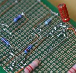
Make a schematic by following your build's connections, see if there is a mistake in the execution or in some value. Show it here too. Does it have a dummy load when measuring? Are the 2 Mosfets fully isolated? Gate stoppers really near to gates? R8 1K? 1.2R is easy to tame, lets debug. Nice and clean work by the way.
Salas,
I put a 100R 3W as the dummy load. Mosfets are fully isolated. Gate stopper is not far from the gate. (1~2cm maybe?) R8=1K. I even switched the 9540 to 9610. After all, it still oscillates! I will try to trace the connections and draw it on a paper. The circuit is based on this schema. I modified the layout, so that the space and length for 4.7uf pp is sufficient.
An externally hosted image should be here but it was not working when we last tested it.
Last edited:
Use the proper film cap C3, we don't know the ESR of a 4u7 BG lytic there. Use 9530,40 Q5 not 9610. But 9610 Q1! Lower R6 to 2K2 when 5V app. Check around the Jfet cascode and the BJT driver Q6 for the output Mosfet that there are no pin reversals and connections are right.
Salas,
have you built a 5V regulator with q9 drawing ~160uA.
I have not, but I can't see the circuit as posted working correctly.
have you built a 5V regulator with q9 drawing ~160uA.
I have not, but I can't see the circuit as posted working correctly.
I have built the circuits I posted in #3200. The 5V with 27K are only reported by others here. He can go 10K and see. I mostly suspect the 4.3K and the CCS practical implementation, the 4u7 lytic's ESR also (C3). IF Q1 is indeed 9540 as depicted in above schema, is highly suspect.
Hi Salas,
As for C3, I got 3.3uf Silmic 2, 4.7u OSCON and 4.7u BG N. The largest film I got is Rifa 450 1uf. Q1 is surely 9610 as you mentioned in other post. Last time, I tried 9540 for Q1 and it did not help. Follow your instruction, I tried 2.15K for R6(2*4.3k), vout becomes 3.85v oscillated and it can't be ajusted through VR!
As for C3, I got 3.3uf Silmic 2, 4.7u OSCON and 4.7u BG N. The largest film I got is Rifa 450 1uf. Q1 is surely 9610 as you mentioned in other post. Last time, I tried 9540 for Q1 and it did not help. Follow your instruction, I tried 2.15K for R6(2*4.3k), vout becomes 3.85v oscillated and it can't be ajusted through VR!
Weird, orelli's works with 1k8 R6. Must be something layout practical that bugs. Q6 should be intimate to Q5. Is it? Try to have their +V pins junction physical point the same. Is that horizontal resistor the R5, and goes all the way long pins from Q6 to Q5, and R6 isn't at the emitter junction as it should but comes later, the one light blue with yellow band? Check and fix such details. Use the Rifa also.
Attachments

hi Salas, I agreed with you , the layout of Canvas maybe is the cause of oscillations. Too long are the resistor's leads; they can works like antennas and suck the very hi frequencies. I realized the 5V version 1.2r working on the layout that you posted on this thread. Sorry, I don't remember the nr post, but it was a dual type(v+ and V-), and it was black with the rails orange, and realized by a friend of you.It was a 1.2 version,not a revisited one.I hope you understood.
I've modified the 1.2 in 1.2r (very simple job) and realized the CCT on a 2mm teflon board. The cct like exactly the one you posted. I used Mundorf MCap for the 4.7 value,
IRF 8A fred diodes and Pan FC in the raw supply. I used cheap film resistors.
And finally the sound! I'm VERY satisfied! The sssv1.2r substitute a TPA Placid shunt reg to feed a Buffalo II with own Trident shunt regs mounted on it. The first 2 things I noted
was dynamic and soundstage. These are a lot better than a previous reg, and remain the same also at very loud volume. After 20 or so hours, the CCT revails also the fine nuances that aren't so apparent at first listening.
I don't check about oscillations,cause, sincerly I don't care(and I've not a oscope).
Thanks again
It would not play without strong stability problems if it was oscillating, especially if feeding analogue there is wide spread harmonic noise all over an FFT I.e. strong hum & buzz masking noise on the speakers, inescapable & equivalent to no go. Nice that you like it subjectively also. Congrats. Maybe you can post front and back pictures that may help others for constructing if you got a camera or a capable cellphone. Regards.
Hi Canvas
Make it tighter... I had the same issues and solved everything by making the smallest possible connections.
Can you draw your layout in a paper so we can follow the gnd connections too ?
Make it tighter... I had the same issues and solved everything by making the smallest possible connections.
Can you draw your layout in a paper so we can follow the gnd connections too ?
Hi Canvas
Make it tighter... I had the same issues and solved everything by making the smallest possible connections.
Can you draw your layout in a paper so we can follow the gnd connections too ?
Thanks for the advise. The reason for long trace is that I need to reserve the space for 2 4.7uf pps. Those caps are big and long, and I have limited space inside the chassis. I am still trying to label each pin on the graph. I will post it later.
picture
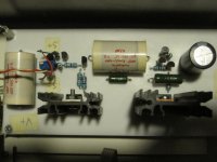
Vout at left, Vin at right. Sense are the red-white twisted pair. The lytic is at the input (4700/16).
The lytic (47uF) is not on the board, but is directly soldered to the PS input terminals of dac.
Vout at left, Vin at right. Sense are the red-white twisted pair. The lytic is at the input (4700/16).
The lytic (47uF) is not on the board, but is directly soldered to the PS input terminals of dac.
Attachments
Last edited:
Looks like a Teflon board? Thanks for the pic. I believe the patterns are relative to what I posted right above. Given the chance, let me remind if there are long cables between the trafo-rectifiers-filter cap to the reg in (when with separate housings especially) a 100uF low ESR lytic from reg's DCin to GND locally to its input terminal or near enough is beneficial.
Correct, it's a 2mm thick teflon board. The pattern are relative at the #1898 post ; ok, this is a normal 1.2 v, but I deleted 33p and 1k and,changed the zobel and the film connected to +RS and K170, et voila', I get the "r" version.I think this attachment is very useful cause there are the holes that simplify very much the work. Before I populate a holed board,then I marked with a red pencil the holes with components and finally I put the holed board upon
the teflon board and drill it.
Trafo-bridge-filter cap are housing apart, and connected to reg with a meter of cable.
Yes ,yesterday I put a BG 220/16 at the reg input and I get an upgrade in the sound,
specially in the treble region(less grainy,more rifined)
the teflon board and drill it.
Trafo-bridge-filter cap are housing apart, and connected to reg with a meter of cable.
Yes ,yesterday I put a BG 220/16 at the reg input and I get an upgrade in the sound,
specially in the treble region(less grainy,more rifined)
Correct move, it decouples the cable run. All well then.
P.S. The pattern you mentioned is from HiFiNutNut's pioneering test job. Bill was the proto tester for 1.2 Low symmetric. He contributed a lot towards a well functioning and also subjective beta in his complex large format system. A fine contribution.
P.S. The pattern you mentioned is from HiFiNutNut's pioneering test job. Bill was the proto tester for 1.2 Low symmetric. He contributed a lot towards a well functioning and also subjective beta in his complex large format system. A fine contribution.
Hi RCruz, I purchased teflon in a warehouse of plastic material. The problem is that I take a
piece of 120x60 cm, the minimum dimension buyable. I don't etch it . I made the connexions
with wire (always with the lead of resistors or capacitors).This is pure Teflon, not the Teflon renforced of Borbely Audio. The board are not rigid, and you have to provide more header to sustain it.
ciao, Orazio
Hi Salas,
I finally solved my problem! The 2N5458 was in wrong polarity. When reversed, the oscillation was gone. I am now using OSCON(!) for C1,C2, and C3 without any problem. I can't wait to see the result. Thank you.
I finally solved my problem! The 2N5458 was in wrong polarity. When reversed, the oscillation was gone. I am now using OSCON(!) for C1,C2, and C3 without any problem. I can't wait to see the result. Thank you.
Last edited:
 Let us know further.
- Status
- Not open for further replies.
- Home
- Amplifiers
- Power Supplies
- The simplistic Salas low voltage shunt regulator