Somebody, who built this circuit with IRFP9240 and IRF9610 also - could reply, which fet is better?
I'm asking that, because the input capacitance of IRFP9240 (1400pF) is nearly 8x higher than of IRF9610 (170pF).
Target usage: +-15V, max 100mA (low voltage and low current).
I'm asking that, because the input capacitance of IRFP9240 (1400pF) is nearly 8x higher than of IRF9610 (170pF).
Target usage: +-15V, max 100mA (low voltage and low current).
Somebody, who built this circuit with IRFP9240 and IRF9610 also - could reply, which fet is better?
I'm asking that, because the input capacitance of IRFP9240 (1400pF) is nearly 8x higher than of IRF9610 (170pF).
Target usage: +-15V, max 100mA (low voltage and low current).
For the latest Salas V1.2R shuper shunt reg. for positive I use IRF9610 for Q1 + IRF9240 for Q6 & for negative IRF610 + IRFP240, wich current drawn your load? wich be tue use I/V, DAC, phono, etc?
Last edited:
update on Fairchild Fets
Salas,
I've gone back into the simulations for V1.2 to try out different Fairchild Fets. Using your criteria from post 3108 ( or there abouts ) I looked for two types of devices;
For the ccs ones that have low Crss@ Vds of 10v
For the other, fets that have low Crss@Vds of 60v
What I found was:
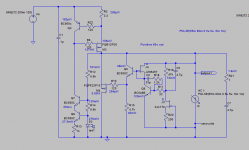
For the Positive regulator, FQB12P20 at the ccs; Crss @ 10v 250pf Gfs 40v, 5.75A, 6.4 S (note, I didn't find a model for it, but, the FQP17P10 has very similar specs with a bit higher Gfs of 8.25A, 9.9 S
and FQPF22P10 or FQP22P10 for the other; Crss @ 60v 160pf, Gfs 40v, 6.6A, 11 S
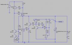
For the Negative regulator, FQP19N20 at the ccs; Crss @ 10v 125, Gfs 40v, 9.7A, 14.5 S
and FQA28N15 for the other; Crss @ 60v 50pf, Gfs 40v, 16.5A, 20 S
I've attache the schematics and the AC analysis.
I think it looks pretty good, but, I've been wrong more than right. Your thoughts...
Ken
Salas,
I've gone back into the simulations for V1.2 to try out different Fairchild Fets. Using your criteria from post 3108 ( or there abouts ) I looked for two types of devices;
For the ccs ones that have low Crss@ Vds of 10v
For the other, fets that have low Crss@Vds of 60v
What I found was:
For the Positive regulator, FQB12P20 at the ccs; Crss @ 10v 250pf Gfs 40v, 5.75A, 6.4 S (note, I didn't find a model for it, but, the FQP17P10 has very similar specs with a bit higher Gfs of 8.25A, 9.9 S
and FQPF22P10 or FQP22P10 for the other; Crss @ 60v 160pf, Gfs 40v, 6.6A, 11 S
For the Negative regulator, FQP19N20 at the ccs; Crss @ 10v 125, Gfs 40v, 9.7A, 14.5 S
and FQA28N15 for the other; Crss @ 60v 50pf, Gfs 40v, 16.5A, 20 S
I've attache the schematics and the AC analysis.
I think it looks pretty good, but, I've been wrong more than right. Your thoughts...
Ken
Attachments
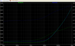
I like the fact that the strong transconductance of the shunt part lowers Zo significantly for a large portion of the audio band VS the IRFP9240 chart I attach, but I don't like the rather early rising trend take off point of it. Then again those are just LT Spice predictions, the real behaviour of parts and layout could even lead to oscillations with Mosfets not used yet, before even going into finer aspects at all. It remains you test in practice with those and find it stable and nice subjectively. I would trust 1.2R for more predictable stability with a wider range of Mosfets. Two TL431 in Totem arrangement, one variable, and 1000uF bypassing them, plus a 4u7 PP, would give good drift & noise performance for 60V Vref also.
Attachments
Hello Salas,
while thinking about building the 1.2Vr reg., there are some questions left.
- In case i have a lot of matched bjts and jfets, what is the ideal idss/hfe
for q2, q3, q4, q6, q7, q9?
- for R2/3/7 will you see a problem if i´d use 150r or 100r ? ´cause i have
no noninductive 120r at hand.
- is it necessary to be exactely 1,8V on spot at led1?
- are the transistors running very hot? will a copperplate 5mm*210mm*135mm
be enough as heatsink?
- do you think blackgate n 4,7/50V will work as c1 and c3?
- what abour r13? any recommendations?
Greetings Ulf
what is the range of supply voltage, what is the current?- are the transistors running very hot? will a copperplate 5mm*210mm*135mm
be enough as heatsink?
Without these it is impossible to give anything other than a guess !
Hi Andrew,
my salas njfet RIAA draws around 0,027 A each channel and i want to
give each channel his own reg.
I´m using 36Ac Transformer, that is arround 50Volts after regulation.
Between the two filter ´lytics i´ll burn down around 5 Volts. So before
the regulators there will be 45Volts.
greetings Ulf
my salas njfet RIAA draws around 0,027 A each channel and i want to
give each channel his own reg.
I´m using 36Ac Transformer, that is arround 50Volts after regulation.
Between the two filter ´lytics i´ll burn down around 5 Volts. So before
the regulators there will be 45Volts.
greetings Ulf
Hi Andrew,
i think i don´t understand you.
I thought for best performance one has to build the v1.2r regulator
as per the schematics. So what would you suggest to be best current
on ccs when each stage pulls 27mA?
And the supplyvoltage at my preamp is 36Volts...no range.
Greetings Ulf
i think i don´t understand you.
I thought for best performance one has to build the v1.2r regulator
as per the schematics. So what would you suggest to be best current
on ccs when each stage pulls 27mA?
And the supplyvoltage at my preamp is 36Volts...no range.
Greetings Ulf
if your mains transformer is a 230:36Vac transformer it will supply 36Vac when the mains input voltage is 230Vac and the load draws exactly the rated AC current.
Your range of mains voltage will vary either side of 220Vac. What is your mains electricity voltage supply range? here in the UK it is 216Vac to 254Vac.
The transformer will deliver more voltage than it's rated 36Vac when the load current is lower than the rated current.
The transformer regulation gives you/us the answer on how far the secondary voltage could rise. That change has to be included in the range that the variable mains has already given you.
You have chosen to use a Shunt regulator with your amplifier.
You have to make the informed decision on what CCS current you want/need to run to give you the performance that you want/need.
Ask the Forum if you cannot make that informed decision.
To give a useful answer to your operating temperature question, you/we need to know the normal and the worst case power dissipations of the big FETs. P=V*I.
you/we need V and I to determine power dissipations and from there give guidance on whether the copper plate will give an acceptable operating temperature.
- Status
- This old topic is closed. If you want to reopen this topic, contact a moderator using the "Report Post" button.
- Home
- Amplifiers
- Power Supplies
- The simplistic Salas low voltage shunt regulator