I've been trying to work that out, too. There aren't a lot of 220-packaged BJTs with similar specs to the good old 2907. I only need 100mA for this application. If I needed higher power, I might parallel them instead. you can parallel as many CCS as you want in this application. It's harmless.
Yes, it was, but then I noticed that BCW68G, while a nice device, is only available in the SOT-23 package and the thermal resistance is too high.
I'm leaning toward PZT2907A in the SOT-223 package, which has better thermal properties. How much current do you need in your application? My power needs are somewhat low because I have a 12V input and a 9V output, only a 3V Vce drop.
The valuable characteristic in the CCS pass device is low capacitance.
jwb said:The ripple rejection on this one is about 1000x better.
Nice variation, I tried something like this one too, but didn't get such good results. Your circuit does not show 1000x better results. I can post the plot. It has better results in the higher frequencies 1kHz up.
If you replace the top 2k resistor with a 2sk170 you'll get even better results.
In real life it oscillates very easily. Modified it a bit and it stopped oscillating but it doesn't seem to perform as well as the alternative I have. jwb, it looks like a promising circuit, perhaps you can make it work. One of the problems is that for a 24V output version the pass bjt needs to dissipate about 750mW. Too much for a single 2N2905A. I did parallel it with another, with emitter degeneration, then it was ok. However, the circuit needs a bit more work.
jwb said:You didn't leave out the base stopper on my Q3 did you? Without that it does certainly oscillate easily. I have it breadboarded here and it's not oscillating, or it's oscillating at a frequency well above 400MHz.
Stopper was in place, of course. I should say that I didn't have the BCW68G and 2n2907 so I used 2n2905a and bc560c respectively. In simulation both work well. Oscillation was below any megahertz value, visible on the oscilloscope. Have you implemented it using exactly those parts shown in your schematic?
Re: Line regulation, R5 bypassed
I take it some simulators don't actually do checks to ensure that a circuit will actually work.
There is something wrong with the model or simulator if it describes the performance you quote here.
Firstly the voltage reference setup by the LED on the op-amp -ve ip is about 1.1 volts (ref. to data sheet) with around 3.4mA through it. That is (17V(reg)-1.1V(LED))/4k7. The dynamic impedance of the LED at this current is around 11ohms. C246 and C220 are incorrectly placed in the circuit. They will increase +ve feedback to the reference possibly introducing oscillations but also give some current compliance issues into the LED for AC conditions. With them removed there is a supply rejection ratio of around 52.6dB at the reference. This can be improved by using a current source in place of R296 but may not offer much improvement sonically.
The DC gain of this circuit is not right for a 17 volt op. With the LED at 1.1V and the gain setting ratio of R242-R243 the o/p is 27.9 volts. R242 should be 1k88 for 17V o/p
What about the noise. Yes, as some OP mentioned the gain setting loop resistors give gain which includes i/p referred noise gain as they always do in traditional feedback type amplifier circuits. The predominant noise sources in the circuit will be the LED, the op-amp input noise and the resistor noise R243//R242.
AC bypassing R242 will reduce HF noise but may increase instability if the op-amp is not stable at low closed loop forward gains.
Some further noise reduction for the LED reference could be done using an RC network.
Some extra stability (phase margin) could be achieved by placing a parallel LR circuit in series with the reg o/p and the decoupling caps and load.
I would prefer a bipolar for the shunt element due to its lower inter electrode capacitances and therefore better phase margin and stability.
syn08 said:Line regulation, R5 bypassed. Which one would you take?
Vertical scale is in dB.
I take it some simulators don't actually do checks to ensure that a circuit will actually work.
There is something wrong with the model or simulator if it describes the performance you quote here.
Firstly the voltage reference setup by the LED on the op-amp -ve ip is about 1.1 volts (ref. to data sheet) with around 3.4mA through it. That is (17V(reg)-1.1V(LED))/4k7. The dynamic impedance of the LED at this current is around 11ohms. C246 and C220 are incorrectly placed in the circuit. They will increase +ve feedback to the reference possibly introducing oscillations but also give some current compliance issues into the LED for AC conditions. With them removed there is a supply rejection ratio of around 52.6dB at the reference. This can be improved by using a current source in place of R296 but may not offer much improvement sonically.
The DC gain of this circuit is not right for a 17 volt op. With the LED at 1.1V and the gain setting ratio of R242-R243 the o/p is 27.9 volts. R242 should be 1k88 for 17V o/p
What about the noise. Yes, as some OP mentioned the gain setting loop resistors give gain which includes i/p referred noise gain as they always do in traditional feedback type amplifier circuits. The predominant noise sources in the circuit will be the LED, the op-amp input noise and the resistor noise R243//R242.
AC bypassing R242 will reduce HF noise but may increase instability if the op-amp is not stable at low closed loop forward gains.
Some further noise reduction for the LED reference could be done using an RC network.
Some extra stability (phase margin) could be achieved by placing a parallel LR circuit in series with the reg o/p and the decoupling caps and load.
I would prefer a bipolar for the shunt element due to its lower inter electrode capacitances and therefore better phase margin and stability.
Craig, I cannot agree more with you about the disparity between simulation and reality. I still do quite a bit of simulation to test out ideas, but always go to the soldering iron for a reality check.
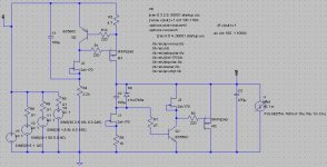
If you feel like it, would you please comment on the circuit attached? While it is not the most extraordinary in simulation it does have good results there too. However, in reality it performs very well. (For outstanding simulation results I posted a circuit earlier, unreal, really.) Do you see any possible areas where we could improve? Thanks in advance.
If you feel like it, would you please comment on the circuit attached? While it is not the most extraordinary in simulation it does have good results there too. However, in reality it performs very well. (For outstanding simulation results I posted a circuit earlier, unreal, really.) Do you see any possible areas where we could improve? Thanks in advance.
Attachments
It's great to see all these nice simple ccts that do the job well and also sound good.
Perhaps the R4 could benefit from some more attention.
Add a small resistor (0.1 - 1 ohm) from o/p rail to M2 so you can actually measure the shunt current - won't effect the result.
IRFP9610, etc?
Have youb tried feeding this with a simple series reg (low ripple), or alternatively, with a Cmultiplier (high Z)?
Generally, good sound results for small number of extra components.
ikoflexer, you were right about the oscillation. Mine was free-running at about 10MHz. That was with PN2907A in both positions. Shame about that.
I tried your and it looks solid. No oscillation, good transient load response. Wasn't able to measure the input ripple rejection.
I tried your and it looks solid. No oscillation, good transient load response. Wasn't able to measure the input ripple rejection.
Let's not lose hope jwb, perhaps it can be fixed; it looks so good in simulation. I can confirm that I could not stop it from oscillation, and I've tried a number of things. You're probably a step away from great success.
This other circuit, the "solid" one, you can blame salas for the original design I only tweaked here and there. This is the one I am using at the moment, it is appealing on many levels; in fact I couldn't stop using the prototype. BTW, have you listened to it with your "noise" headphone thingy? With a proper board layout and case should be even better. PCB layout design may be in the works soon (for through the hole parts), but I'm also personally thinking of going the smd route for this one; maybe.
I'm also thinking of putting together a Dennis Colins noise amp, as I'm having problems gauging the performance of this regulator.\
Let's keep the fire going, good discussion, thank you all for your comments!
This other circuit, the "solid" one, you can blame salas for the original design
I only tweaked here and there. This is the one I am using at the moment, it is appealing on many levels; in fact I couldn't stop using the prototype. BTW, have you listened to it with your "noise" headphone thingy? With a proper board layout and case should be even better. PCB layout design may be in the works soon (for through the hole parts), but I'm also personally thinking of going the smd route for this one; maybe. I'm also thinking of putting together a Dennis Colins noise amp, as I'm having problems gauging the performance of this regulator.\
Let's keep the fire going, good discussion, thank you all for your comments!
ikoflexer said:This other circuit, the "solid" one, you can blame salas for the original design
I plea guilty!

- Status
- This old topic is closed. If you want to reopen this topic, contact a moderator using the "Report Post" button.
- Home
- Amplifiers
- Power Supplies
- Best low noise regulator?