Yes, when talking peak to peak swing figures.Today I wired the regulator to the tube driver stage. My PSU sagged more than simulated with PSUD, so I had to reconfigure the regulator to 190V. The feeding voltage is 210V. It's okay right now. I didn't put the scope to test yet, I'd like to do this after final assembly.
The tube is biased at -2Vg /24mA. It will swing to 45mA max. 65mA of shunt current should be enough for headroom, right?
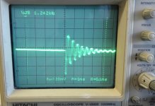
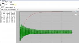
I just finished building my second SSHV2 following the first successful build. Now I have problem this time. After connectign it to the same preamp for testing, I've got a lot of noise from my speakers of both channels. It seems something is in oscillation. The preamp works fine with other SSHV2 I build. So the problem must be the SHHV2 I just did. I used same PCB/parts as the first time. Attached is the output wave form from my scope. Both channel have the same wave form outout and inputs are all granded. I have CRC on the SHHV2 board and very close to the CCS. The reg output voltage looks ok and stable. What the problem can be?
Attachments
Maybe C1 or C2 is touching some pads under it? I don't know if your home made PCB has those multi size pads too. Something regarding the sinks and insulations? The other build had grounded sinks? Add a small filmcap directly over the input connector and/or up the Q1 & Q2 gatestoppers values if the cause remains elusive. The BJTs used are from the same batch/vendor?
The other build has sink not grounded, and I have tried 0.1uf film cap but it does not make any change. From memory, it seems all commponents used are the same from same batch except C1. In the othet build I used Wima MKP4 for C1,but MKP10 in this build. Could that be a problem? I will replace them with MKP4 and see tomorrow or I will try to increase gatestopper value for Q1and Q2 as you suggested. Thanks.
Last edited:
Fixed problem ! It was my silly mistake. I did not ground the input board of the preamp, that has relays for singnal selections. On the board there is a 555 based timer as well for output delay and mute. I think the timer was radiating when the board was not grounded. Thanks Salas for help.
You found it yourself, I only mentioned possible grounding differences in general. Well done.Post a pic if you got. Everybody likes tube builds.
I just have some photos before the reg. was put in the preamp. My first build used homebrew PCB, this one uses factory made.
Attachments
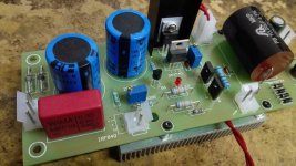
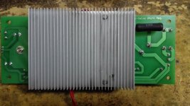
yes, two separate 2pin connectors ,one near IRF840 and the other near the black sink are sense and force. 4X4007 is for a 7805 supplying 5V for relays, the 2X gray bub diodes is the full wave rectifier connected to a CRC filter supplying about 340V raw DC to the reg. I use two regs, the heater supply is on the other reg. Heater supply is elevated and voltage is just taken from the output of the reg. All in 2 boards ! ")
Last edited:
Is there a path that the secondary supply for relays was returning a ground correlated to the HV ground on the same board so the timer's noise went back there when the input board was non grounded? Or that secondary supply has its own isolated ground non related to the HV section?
It's a bit complicated, let me explain:
The secondary supply for the relays was isolated to the Reg ground before I fixed the problem. But one of the pins of the output mute relay ( timer controlled ) is connected to the ground at output RCA ground, where the Reg ground connected straight to .
The ground of input board is not connected to the output ground. What I did was : 1) grounded the negative supply for relay to ground ( that made no change) 2) grounded the polygon plane part of the input board , all the sudden, noise killed !
Quite a sneaky timer noise that was. So two times you made it right after it was wrong. First with the fakes, second with the paths and 555. Good score. I hope you enjoy the valve preamp now better than before the shunt PSUs and it was worth the effort. Show us the full preamp sometime. Take care.
Quite a sneaky timer noise that was. So two times you made it right after it was wrong. First with the fakes, second with the paths and 555. Good score. I hope you enjoy the valve preamp now better than before the shunt PSUs and it was worth the effort. Show us the full preamp sometime. Take care.
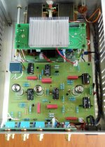
yes, SSHV2 makes the preamp so much better, definitely worth the effort. Here is my preamp in the photo
Attachments
Hi Salas.
I've purchased a SSHV2 via Tea-Bag. Is there any guidance for the raw DC supply to the SSHV2?
My target output from SSHV2 is 250V @ 45mA (including 20mA for shunt).
I'm planning on a Schottky bridge rectifier and 660uF 450V electrolytic cap. Does that sound OK.
Cheers
Ray
I've purchased a SSHV2 via Tea-Bag. Is there any guidance for the raw DC supply to the SSHV2?
My target output from SSHV2 is 250V @ 45mA (including 20mA for shunt).
I'm planning on a Schottky bridge rectifier and 660uF 450V electrolytic cap. Does that sound OK.
Cheers
Ray
Is there any guidance for the raw DC supply to the SSHV2?
Raw supply voltage will be 30-40V greater than SSHV2 output. Thus CCS upper FET dissipates (for example) 40V*45mA~ 1.8W.
Attachments
Raw supply voltage will be 30-40V greater than SSHV2 output. Thus CCS upper FET dissipates (for example) 40V*45mA~ 1.8W.
Thank you, but I got that from the manual. What I was asking is if there is an optimal level of capacitance to apply between the bridge rectifier and the SSHV2.
Ray
Many have used CRC or CLC with 220uF final capacitor and it was good for ripple but there is no strict rule. See to have no significant Q peaks in the PSU analysis to avoid create bad transients and use bleeder resistors across ensuring the HV capacitors discharge after power off. 20VDC in-out drop over the reg is enough, avoid extra dissipation on Q1 that way. Can burn more on R if CRC.
Its possible, but takes some help like using TO-126 sinks on Q4 Q5, 82K 2W R9 R10, and be ready to manage 8W dissipation for Q3 at 26mA CCS. C1 C2 must be 450V or higher of course and must watch the setting procedure and input transients so to not overexpose Q1 etc. Use resistor bleeders across the HV capacitors of the raw supply if not already. Isolation and cable ratings as well as handling must be careful too. Easier to arc.
- Home
- Amplifiers
- Power Supplies
- Simplistic MosFET HV Shunt Regs