Many have used CRC or CLC with 220uF final capacitor and it was good for ripple but there is no strict rule. See to have no significant Q peaks in the PSU analysis to avoid create bad transients and use bleeder resistors across ensuring the HV capacitors discharge after power off. 20VDC in-out drop over the reg is enough, avoid extra dissipation on Q1 that way. Can burn more on R if CRC.
Thank you Salas
Cheapest way to get high current output
I have seen this circuit http://www.antiquewireless.org/uploads/1/6/1/2/16129770/37-a_solid-state_filter_choke_or_field_coil_replacement.pdf and it crossed my mind that we could get a higher current output by exchanging the TIP50 with one BUV 21/22 http://www.onsemi.com/pub_link/Collateral/BUV22-D.PDF
Could you guys please point me out if this is an easy task of just changing resistor values or there's any other way to do it?
Also, what could be the expected current output as this power transistor has a 250W dissipation capability?
Cheers and thank you for the help")
I have seen this circuit http://www.antiquewireless.org/uploads/1/6/1/2/16129770/37-a_solid-state_filter_choke_or_field_coil_replacement.pdf and it crossed my mind that we could get a higher current output by exchanging the TIP50 with one BUV 21/22 http://www.onsemi.com/pub_link/Collateral/BUV22-D.PDF
Could you guys please point me out if this is an easy task of just changing resistor values or there's any other way to do it?
Also, what could be the expected current output as this power transistor has a 250W dissipation capability?
Cheers and thank you for the help
Attachments
I'm not sure if it is suitable in the thread...
You cannot use BUV22 in the design with the voltages from the schematic as soon as the max Vceo must not exceed 250V (vs. 400V for TIP50).
The design itself highly depends on the hfe for the input ripple filtering (which is again smaller for the BUV22[20] than for TIP50[30]) and usually do not achieve such remarkable results as mentioned in the corresponding text. More than that: the output impedance is much higher then in the Salas' design. I think Salas' design will outperform the serial regulator to great extend.
P.S. Well... forgot to mention. The resulting (collector) current will be hfe times higher than control (base) current. LR8N can deliver 10mA. According to the BUV22 datasheet hfe for the currents less than 10A is in the margins of 20 - 60. So - max output current will be estimated as 200-600mA.
You cannot use BUV22 in the design with the voltages from the schematic as soon as the max Vceo must not exceed 250V (vs. 400V for TIP50).
The design itself highly depends on the hfe for the input ripple filtering (which is again smaller for the BUV22[20] than for TIP50[30]) and usually do not achieve such remarkable results as mentioned in the corresponding text. More than that: the output impedance is much higher then in the Salas' design. I think Salas' design will outperform the serial regulator to great extend.
The 250W dissipation is mentioned for Tc = 25C. A glimpse on what is really achievable is on the page 3 top (Figure 2 and the text to the right). Assume the max safe input voltage of 227V (which gives us 10% margin for overvoltage), min voltage across the regulator 15V, possible 5% undervoltage protection - 12V: we will have 50V across the transistor in worse conditions (neglecting the startup procedure). It gives us slightly more than 1.2A of allowable current for max output of 200V. There should be a HUGE heatsink as you are going to dissipate 60W of power. The performance will be slightly flawed too.Also, what could be the expected current output as this power transistor has a 250W dissipation capability?
I doubt you ever need to change the resistors. You can just put the BUV here and get around the same voltage (plus-minus 2-3V). BUT you have to take into account all the limits mentioned above.... if this is an easy task of just changing resistor values or there's any other way to do it?
P.S. Well... forgot to mention. The resulting (collector) current will be hfe times higher than control (base) current. LR8N can deliver 10mA. According to the BUV22 datasheet hfe for the currents less than 10A is in the margins of 20 - 60. So - max output current will be estimated as 200-600mA.
Last edited:
Hi Salas,
I built and had this regulator working (CRT layout, teabag GB) to power Impasse preamp but with dropping resistor between raw input and SSHV2. Raw DC input was 560Vdc so I used 2.8K 40W power resistor to drop to 380Vdc. Vout result was 350Vdc as required for Impasse. RLoad was 6k 30W. I did not like the heat on power resistors so I decided to reduce transformer winding ended up having target 380Vdc raw input, measured exactly as needed for SSHV2.
When I connected the new transformer, Q1 popped, R1 burned and output was dead. I had replaced Q1, Q2 and Q3. Learned my lesson, now I used Variac to slowly increase Vin and noticed R1 is heating up due to increasing voltage drop.
Initial check on all components looks okay.
I'd like to test first CCS to find out why R1 is heating and so much Vdrop on R1. Can I connect first F+ and F0 with RLoad ?
Or, do I have to lift R6 and Q3 to isolate the rest from CCS?
Roland
Last edited:
Roland hi,
So it worked before with the Rdrop but it went bad with the new Tx. Was the cabling to its input drastically altered?
Follow this troubleshooting example exchange. Has steps on how to test the separate sections: http://www.diyaudio.com/forums/powe...tic-mosfet-hv-shunt-regs-448.html#post4109381
It could be oscillation though. If input wiring is the culprit, bypass with a cap right at the raw dc input connector.
Andrew,
That's what immediately comes to my mind.
Vdrop resistor could have been useful absorbing the stress, but since I removed it - nothing was there to protect it.
I am very sure nothing was changed because it worked the first time.
Salas,
Could you please check the link you posted or maybe please let me know which starting post number.
Tried searching the thread since this morning but this thread has grown. I am now in page 100 and still searching. I'll double check C1 is mounted properly tonight.
Thank you.
Counting...
It seems too small according to the recommendations.
Means that the Iload must be 58mA.RLoad was 6k 30W. Vout result was 350Vdc...
Iccs = 64mARaw DC input was 560Vdc... 2.8K... 380Vdc
It seems too small according to the recommendations.
It's not exactly like that, because at the start up the input voltage is also sit at zero. The CCS starts conducting rather quickly, having the load resistance in the output we have almost all the input voltage on the output load.the output is sitting at zero volts before power ON.
The CCS sees the full input voltage and the zero output voltage as the Vdiff during start up.
I doubt it... Something is wrong with the input or output circuits if the middle (SSHV) was not touched.Vdrop resistor could have been useful absorbing the stress, but since I removed it - nothing was there to protect it.
Last edited:
Salas,
Could you please check the link you posted or maybe please let me know which starting post number.
Tried searching the thread since this morning but this thread has grown. I am now in page 100 and still searching. I'll double check C1 is mounted properly tonight.
Thank you.
#4478
Since the original 2SK117GR are rather scarce nowadays, I'm looking for an alternative. Salas said in earlier post that 2SK880GR would be okay. I suppose they should also be ~4 mA IDSS? How large batch you recommend getting for measurement in order to get one with the right IDSS?
I also got some 2SK117GR:s coming from eBay (not from China) that seemed genuine. However can't be sure so better prepare for them being fake.
I have a tube preamp running 270 V; 34mA and a transformer with 280 V; 0.15A secondary and solid state rectification. Any suggestions on CRC filter design?
I also got some 2SK117GR:s coming from eBay (not from China) that seemed genuine. However can't be sure so better prepare for them being fake.
I have a tube preamp running 270 V; 34mA and a transformer with 280 V; 0.15A secondary and solid state rectification. Any suggestions on CRC filter design?
Telec, the most SMT samples you will chance on will have enough IDSS to provide 270V in combination with the double 68K resistors. 10pcs will be enough to narrow some between 3-5mA anyway.
For any K117GR from ebay, post a macro picture here before applying it. We should be able to recognize fakes.
For any K117GR from ebay, post a macro picture here before applying it. We should be able to recognize fakes.
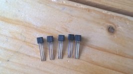
Toshiba had different 117 font print. "1" was like "l", "7" had a slightly curvy leg part. The print color was brownish (laser etched). The shape and proportion of the plastic head is alright though. The pins length and their flattened neck part look good also. Either a fake or an unusual old batch. The print reminds more of Toshiba transistors like the 2SC/2SA series.
Attachments
Measure the Vp and Idss and compare to what would be expected.
Borbelly gives the formula relating gm to Vp.
gm = -2*Idss/Vp*[1-Vgs/Vp] (Vp = Vgs when Id <0.1uA, you cannot read this off the Id vs Vgs graph)
When Id = Idss, Vgs =0 and the last term becomes 1 and thus can be ignored
so the simplified version is
gm=-2Idss/Vp
eg.
for BL
7mA Idss and Vp=0.75V gives gm ~ 19mS
for GR
5mA Idss and Vp=0.65V gives gm ~ 15mS
Last edited:
transformer + rectifier + smoothing capacitor.
Optionally, one can add on RC, or LC, or (L+R)C stages after the first smoothing.
Alternatively, when current demand is low one can adopt choke input filtering and since the load is CCS fed, there are no problems with the choke input falling out of regulation.
Optionally, one can add on RC, or LC, or (L+R)C stages after the first smoothing.
Alternatively, when current demand is low one can adopt choke input filtering and since the load is CCS fed, there are no problems with the choke input falling out of regulation.
- Home
- Amplifiers
- Power Supplies
- Simplistic MosFET HV Shunt Regs