Greetings,
My name is Kevin, 30 years old and I'm from Belgium. I'm going to attempt my first ESL in about 2 weeks but I'm struggling a bit ...
I'm going to build wire stators which are about 1m high and 20cm wide ( open to suggestions about the sizes), and the stator - diaphragm distance is going to be 1mm.
Which type of wire is best for this ?
https://www.elfa.se/elfa3~nl_nl/elfa/init.do?item=55-501-85&toc=20158
https://www.elfa.se/elfa3~nl_nl/elfa/init.do?item=55-501-04&toc=20158
I've read that you can use regular toroids as a step-up, which one is suitable for this project ? :
Transformatoren - Ringkern Trafo's tot 100W - Ringkerntrafo 80W 2x 6V 6,67A - EOO - ElectronicaOnderdelenOnline
Ringkerntransformator 2 x 6 V 50 VA Sedlbauer Inhoud: 1 st. in de Conrad online shop | 606578
MCTA050/06 - MULTICOMP - TRANSFORMER, 50VA, 2 X 6V | Farnell België
VTX-146-050-106 - MULTICOMP - TRANSFORMER, 50VA, 2 X 6V | Farnell België
2x6V 50VA ringkerntransformator - Ringkerntrafo.nl
Turns ratio of about 1:70 and bias voltage of 3500V.
I have some 10m Mylar with a thickness of 6 µm
If I'm going to make it a hybrid, I'm going to use these (I already own 2 of these): Monacor SPH-130AL 10.3820 - Geronika
I mainly want to build a pair simply to give it a try, if it succeeds I'm going to build me some bigger ones, the reason they don't need the monacor drivers per se is because, if successful, i'm going to use them as rear speakers for my surround setup and they don't need to go very low ...
I'm going to drive them with my Marantz SR7007 receiver
Many thanks in advance already guys, can't wait to start building")
My name is Kevin, 30 years old and I'm from Belgium. I'm going to attempt my first ESL in about 2 weeks but I'm struggling a bit ...
I'm going to build wire stators which are about 1m high and 20cm wide ( open to suggestions about the sizes), and the stator - diaphragm distance is going to be 1mm.
Which type of wire is best for this ?
https://www.elfa.se/elfa3~nl_nl/elfa/init.do?item=55-501-85&toc=20158
https://www.elfa.se/elfa3~nl_nl/elfa/init.do?item=55-501-04&toc=20158
I've read that you can use regular toroids as a step-up, which one is suitable for this project ? :
Transformatoren - Ringkern Trafo's tot 100W - Ringkerntrafo 80W 2x 6V 6,67A - EOO - ElectronicaOnderdelenOnline
Ringkerntransformator 2 x 6 V 50 VA Sedlbauer Inhoud: 1 st. in de Conrad online shop | 606578
MCTA050/06 - MULTICOMP - TRANSFORMER, 50VA, 2 X 6V | Farnell België
VTX-146-050-106 - MULTICOMP - TRANSFORMER, 50VA, 2 X 6V | Farnell België
2x6V 50VA ringkerntransformator - Ringkerntrafo.nl
Turns ratio of about 1:70 and bias voltage of 3500V.
I have some 10m Mylar with a thickness of 6 µm
If I'm going to make it a hybrid, I'm going to use these (I already own 2 of these): Monacor SPH-130AL 10.3820 - Geronika
I mainly want to build a pair simply to give it a try, if it succeeds I'm going to build me some bigger ones, the reason they don't need the monacor drivers per se is because, if successful, i'm going to use them as rear speakers for my surround setup and they don't need to go very low ...
I'm going to drive them with my Marantz SR7007 receiver
Many thanks in advance already guys, can't wait to start building
Hi Kevin,
And I'm no expert so you'd be wise to seek others' advise as well. That said, I have built hybrid ESL's for myself and friends and I will share my thoughts on it with you.
I have no experience with wire stators so I can't advise you on wire choices.
I think any of the transformers you've listed would work (two per speaker with 6v windings in parallel on the amp side, output windings in series, and a 1-Ohm 10W series resistor on the + input). However, I would use one of the single 230V primary transformers, rather than the one with dual 115V primaries.
I think 1 mm diaphragm to stator spacing is too close, even for a hybrid panel, as it would limit excursion and not accommodate the typical build tolerances. Whereas, I think 1.5 mm spacing is would be an optimum trade-off between excursion and efficiency. Also, go with Sanders' Cookbook recommendation to add interim support spacers (or dots) to stabilize the diaphragms; with the span between the supports lot less than 70x or greater than 100x the diaphragm-to-stator spacing.
I think the specs on the woofer match up pretty well to the electrostat, insofar as the low Qts and reasonably low voice coil inductance should provide fast transient speed... especially if you mount the woofer in a transmission line so as not to raise the system Q too much. However, the woofer's size and fs would require adding a subwoofer to play low with authority.
The remaining problem I see is that you want to power the system with a single stereo receiver (?) This would necessitate a passive crossover; which then limits the crossover slope and frequency options. If you use a passive 12db crossover, you would then need to put the crossover frequency at least three octaves above the diaphragm resonance-- around 400Hz minimum, I figure.
I have no idea how to design a passive crossover for an ESL, as the typical crossover design calculators available on the web are useless because they assume the impedance is constant; whereas, an ESL's impedance varies with the frequency. There are other builders on this forum who know how to mitigate the varying impedance and design a workable passive crossover for an ESL, but I'm not one of them.
The crossover design problem goes away and and tuning is much simplified if you can swing the cost to bi-amp the system with an adjustable active crossover upstream of the power amps. You could then tune the speakers by ear in real time and the sound would be superior to a passive crossover.
OK, there's my $.02
Good luck with your project!
jazzman
Hi Jazzman,
I'm going to drive these speakers with my Marantz SR7007 home theatre surround receiver. I will bi-amp them and the receiver also comes with Audyssey DSX. This will measure the room caracteristics and adjust accordingly.
I will go with the 1.5mm spacing and start looking for some wires, do you have any recommendations regarding the transmission line ?
I've visited your website, looks great ;-)
Thanks for your help
Greetings, Kevin.
Might be some useful information here:
http://www.diyaudio.com/forums/planars-exotics/164430-how-construct-cube-louver-acoustat.html
http://www.diyaudio.com/forums/planars-exotics/164430-how-construct-cube-louver-acoustat.html
It is hard to determine exactly which wire to use in your choices.
I would pick the thinnest wire you can providing that its insulation is the thickest.
If the specs are true then I would with the thinner stuff as per test voltage.
However it does not say what the outside Diameter is as this would give you an indication as to how thick the insulation actually is.
I think that your panel size is a very good place to start.
As Charlie mentioned with wire stator's it is very difficult to reach extreme tolorences even if you use a ridged wire rod as I have done here,
A Segmented Stator Desktop ESL
I have as much as 5% error in some points and in past builds as much as 10% to 15% in my D/S spacing, Although they still worked.
Being that you are shooting for a width of 20cm (7.8 inches) you may want to consider electrically segmenting the stator.
This is easily done with this type of construction.
As Charlie mentioned for a 1mm D/S it will be very hard to maintain a good tolerance for this type of construction as I have mentioned above for the width you have choosen.
There have been a few recent projects where one has decided to redo their design because of not being able to get the wires to be perfectly straight, well presistance prevails!!
The other rule of thumb is by Roger Sanders, You don't want to go over the 1:100 width to D/S ratio typically for a 20cm wide panel you want no less than about 2mm of D/S.
Due to the width of the panel this is mostly about mechanical stability.
The other factor to Keep in mind is excursion space and how low of a frequency do you want the panel to produce.
For every octave lower a driver has to produce it takes 4 times the Xmax in order to produce the same SPL's.
Now, about transformers and amplifiers.
Any of the transformers you have listed may work very well.
However this technique of using power transfomer's in reverse have one draw back, They do create a very low impedance on the low end of the frequency spectrum as well.
For a transformer of this type generally if you try to input a frequency much less than about 360Hz to 300Hz it creates a very low impedance to the amplifier and also the transformer starts to go into saturation of the core and this causes lots of audible distortions and havoc for the amplifier.
A properly designed transformer for an ESL won't have these type of characteristics, However they are very expensive to get right now.
Much more than what your Marantz may cost for a complete system.
Typically most (not all) A/V receiver's no mater how much they cost are loaded with chipamps and are not suited for use with speaker impedance's in the 1 to 2 ohm range that ESL's and the associated power transfomer's in reverse present.
Do not despair this does not mean that it won't work (as it will ), But you may not get the most ultimate performance out of it as to what they are capable of.
A dedicated High Power amp that can handle low ohm loads is a better way to go.
As is an active crossover too.
Electrically segmenting the panel helps with the load issue on the high end as well as it increases the horizontal dispersion.
In order to help with the low impedance factor of the transformer at the lowest frequency's is to carefully choose your crossover frequency while mating to your woofer system.
The type of listening environment and size of your room ( or in other word how loud do you want it to be) has a lot to do with your design requirements.
For instant's, This design (I have shown here a few times) was great for what I needed it to do.
A Desktop ESL Build
That last panel did +105db flat 40hz to +20Khz (with a little woofer that could not keep up) at .5 to 1 meter using a cheapy bookshelf AWIA amplifier of 80 watts per channel ( two channels for mono of coarse) and the sound was incredable!!!
So, Yes, It can be done !!!
I used that panel to test the limits of my materials and construction.
It was made in 2003 and it lasted for 10 years before I pushed it to its limits and burned it up.
It was fine the way it was only I pushed it!!
As long as you follow some simple rules a long they way you shouldn't have any problems at all actually.
The thread hella365 posted is a great read to start with, Not to mention many many more!!
Just a few things to think about.
jer
P.S. I have yet to see anyone Fail, Following our Guidelines !!!!
Last edited:
Hi Geraldfryjr,
I'm going to dive deeper into the matter during the weekend and "explore" your link. I think I will follow the advice and adjust the width of the ESL to match the 1:100 d/s ratio.
What I'm looking for is an ESL that is impedance friendly (preferably not below 4ohm), in case I want to build some for my friends if my project succeeds ;-)
I decided upon my trannie already: Transformatoren - Ringkern Trafo's tot 100W - Ringkerntrafo 80W 2x 6V 6,67A - EOO - ElectronicaOnderdelenOnline
Thanks for the help guys.
Greetings, Kevin.
What I'm looking for is an ESL that is impedance friendly (preferably not below 4ohm), in case I want to build some for my friends if my project succeeds ;-)
You could use a higher value series resistor if you're worried about your amp handling the load. My tandem 230V/6V transformer setup is similar to what you're proposing to use. I'm currently using a 1-Ohm 10 watt series resistor on the (+) input and my Carver TFM amps handle the load just fine. I've also experimented with higher value resistors and was surprised to upping the series resistor to 4-Ohms had no audible effect on the character of the sound and only a very slight attenuation. Another builder I know, who uses a similar setup, was so worried about the load that he added an 8-Ohm series resistor and he says it sounds fine.
Last edited:
You could use a higher value series resistor if you're worried about your amp handling the load. My tandem 230V/6V transformer setup is similar to what you're proposing to use. I'm currently using a 1-Ohm 10 watt series resistor on the (+) input and my Carver TFM amps handle the load just fine. I've also experimented with higher value resistors and was surprised to upping the series resistor to 4-Ohms had no audible effect on the character of the sound and only a very slight attenuation. Another builder I know, who uses a similar setup, was so worried about the load that he added an 8-Ohm series resistor and he says it sounds fine.
I had also tried a few different values and didn't hear a difference.
Hi Guys,
I'm currently reading some threads on the forum, ... and there's a lot to read ;-)
It's good to know that adding a higher value resistor doesn't make a huge difference and I'll be experimenting with that.
Charlie, can you explain to me, since I have no electrical background, what the Wattage value behind the resistor value means ? You are currently using a 1-Ohm 10 watt series resistor on the (+) input. Does that mean you can't drive your speakers beyond 10 Watt ? (Meaning you can't turn an amp of, let's say, 2x40Watt halfway open, sort of speech ?)
Thanks for the help.
Greetings, Kevin.
Hi Guys,
I'm currently reading some threads on the forum, ... and there's a lot to read ;-)
It's good to know that adding a higher value resistor doesn't make a huge difference and I'll be experimenting with that.
Charlie, can you explain to me, since I have no electrical background, what the Wattage value behind the resistor value means ? You are currently using a 1-Ohm 10 watt series resistor on the (+) input. Does that mean you can't drive your speakers beyond 10 Watt ? (Meaning you can't turn an amp of, let's say, 2x40Watt halfway open, sort of speech ?)
Thanks for the help.
Greetings, Kevin.
Hi Kevin,
Nothing to worry about. The resistor's rating is not in peak watts, but the amount of heat (in watts) it can dissipate continuously and indefinitely without damage. I use 225 watt RMS/channel amps which, during musical peaks, probably pushes several hundred watts momentarily thru the 10-watt wire wound series resistor, and the resistor does not fail.
Hi Charlie,
Thank you for your help. Because my supplier only has 2 units of my first trannie of choice I'm switching back to the original ones (2x 230V/6V 50VA)
I've read in another thread that you can go as low as ±250Hz with 50VA cores, so they will do fine for me.
http://www.diyaudio.com/forums/plan...lectricity-do-you-need-run-esl-speaker-2.html
I'll continue reading and posting here.
Greetings, Kevin.
Hi Everybody,
Can't believe it's been 10 months since I've posted something here ... Anyway, I've decided that this isn't going to be the final build but rather test panels ...
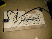
I've build the panels and bias HV supply but I'm struggling a bit ... For the bias I've used a Cockcroft Walton cascade ... I used 27 MKP caps rated for 250V ac/400V DC 0,1uf and 27 1N4007 diodes. I've used 2 small PCB transformers 230V/6V with a 50kohm potentiometer between the secondaries as voltage divider and 8 Mohm resistors in series to limit the current. In theory I can get 6000V out of it but I don't think I'm getting that ... Already at the 4th stage I measured a serious voltage drop ... Which I don't get, I've tested all my diodes and caps and they're still working ...
Anyway I hooked the first panel up and ... It does work, there's sound coming out of it albeit not "that" loud, I have to crank up the volume quite a bit in order to play at a decent level...
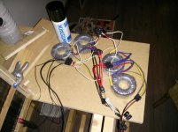
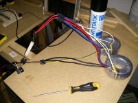
Any thoughts on how I can let them play louder ? I've posted some pictures so you guys know how things are so far.
Greets, Kevin
Can't believe it's been 10 months since I've posted something here ... Anyway, I've decided that this isn't going to be the final build but rather test panels ...
I've build the panels and bias HV supply but I'm struggling a bit ... For the bias I've used a Cockcroft Walton cascade ... I used 27 MKP caps rated for 250V ac/400V DC 0,1uf and 27 1N4007 diodes. I've used 2 small PCB transformers 230V/6V with a 50kohm potentiometer between the secondaries as voltage divider and 8 Mohm resistors in series to limit the current. In theory I can get 6000V out of it but I don't think I'm getting that ... Already at the 4th stage I measured a serious voltage drop ... Which I don't get, I've tested all my diodes and caps and they're still working ...
Anyway I hooked the first panel up and ... It does work, there's sound coming out of it albeit not "that" loud, I have to crank up the volume quite a bit in order to play at a decent level...
Any thoughts on how I can let them play louder ? I've posted some pictures so you guys know how things are so far.
Greets, Kevin
Attachments
Hi,
- don't use wooden material as PCB under HV-conditions.
You may glue the caps -pins up- on a wooden plate with the wiring soldered free-air.
- Two 230/6V trafos won't give You 230V.
Due to the rather large losses of small trafos its probabely ony around 200V.
- I'd omit with the 50k Poti at all.
You need some current to drive the multiplier and Potis wiper don't take currents well.
Also, most Potis are not specced or intended for high voltages.
If You need less output voltage just use less stages of Your multiplier.
If You want to stay with the Poti idea rather use a discrete voltage divider and low ohmic resistors.
- 250/400V caps have insufficient voltage rating.
If they don't already hum like a bunch of bumble bees its probabely due to the high ohmic poti reducing the current.
- use a charge blinker as indicator for leakage in Your setup
jauu
Calvin
Very Cool!!!
The vocals through those things are incredible aren't they ?!!!!!!
jer
@ Jer,
Indeed vocals sound amazing ��
Greets, Kevin
Hi Calvin,
Thanks for your help, I have a few questions for you
Already many thanks for your help
Greets, Kevin
Thanks for your help, I have a few questions for you
Hi,
- don't use wooden material as PCB under HV-conditions.
You may glue the caps -pins up- on a wooden plate with the wiring soldered free-air.
Is there a reason for this ? (I assume there is but I wouldn't know why)
- Two 230/6V trafos won't give You 230V.
Due to the rather large losses of small trafos its probabely ony around 200V.
This is true, I measured about 196V
- I'd omit with the 50k Poti at all.
You need some current to drive the multiplier and Potis wiper don't take currents well.
Also, most Potis are not specced or intended for high voltages.
If You need less output voltage just use less stages of Your multiplier.
If You want to stay with the Poti idea rather use a discrete voltage divider and low ohmic resistors.
The poti is in between the secondaries and aren't getting more voltage than that 6V, will dive deeper into your voltage divider suggestion this evening (and probably the next few days)
- 250/400V caps have insufficient voltage rating.
If they don't already hum like a bunch of bumble bees its probabely due to the high ohmic poti reducing the current.
Which voltage rating do you suggest ? These caps aren't humming ... So far
- use a charge blinker as indicator for leakage in Your setup
jauu
Calvin
Already many thanks for your help
Greets, Kevin
Hi,
- wood behaves dissipative. There´s always some humidity left and its hygroscopic. Methyl-Cellulose for example has been used as diaphragm coating.
- ~200V means +-280Vpeak-to-peak. The caps need to withstand twice the input voltage. So take 630V or 1000V types.
- the poti needs to pass some current. I´d rather use a voltage divider or - limiter on the 230V side of the second transformer, just ahead of the cascade
jauu
Calvin
Hi Calvin,
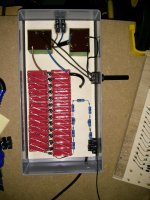
I followed your advice and made a new unit, I've used 0.1uf caps which are rated at 1000VDC - 600VAC everything pins up but I still have a voltage drop ...
I did change the transformers, they're now 230V - 12V 183mA 2.2VA
And the poti has gone from 50kOhm to 1kOhm
Is there a minimum currentrating that the transformers need to be ?
I kept the idea of the poti because it could be handy to regulate the output voltage with a simple turn ...
Thanks for your advice so far in this project.
Greets, Kevin.
Attachments
- Status
- This old topic is closed. If you want to reopen this topic, contact a moderator using the "Report Post" button.
- Home
- Loudspeakers
- Planars & Exotics
- First ESL attempt