I agree they will look better if aligned, but, logically thinking, it seems they would be more efficient if they overlapped.
A few years ago I did run a test comparing response with front and rear wire stators lined up .vs. staggered.
I can't remember the exact D/S and wire spacing, but the wire diameter and spacing between the wires was < D/S.
There was no appreciable difference in efficiency/sensitivity, or distortion.
If the spacing between wires got to be significantly larger than the D/S spacing, most likely there would be some differences between the two cases.
Attachments
In case if there is any interest, All Electronics has these nice toroids:
https://www.allelectronics.com/inde...3345592a403b2f4a37a59384e7ab28f02be1";i:1;N;}
I ordered 8 of them for my bass panels, 4 per side. I'll be using the Antek AN-0506's for the tweeter panels.
https://www.allelectronics.com/inde...3345592a403b2f4a37a59384e7ab28f02be1";i:1;N;}
I ordered 8 of them for my bass panels, 4 per side. I'll be using the Antek AN-0506's for the tweeter panels.
Those will be to small for a bass panel as it takes quite a bit of iron to get satisfactory performance.
In my experiment last year it took stacking 4 cores like that in order to get to the 15hz to 30 hz range and still maintain a decent sine wave at a level of about 100watts.
Still not a bad deal anyhow as I paid about the same for my cores that are about the same size.
Stacking them may yield you the performance for bass that you are looking for using a added primary around all of the cores.
Being that they only have one secondary winding (6v-ct-6v) the transformer capacitance may be low enough for a decent high frequency limit as well.
Mine has three secondary windings and this raised the capacitance considerably.
This is something that will need to be tested,But I am sure that you will need at least 4 of them for bass though.
There better alternatives for that kind of cost using transformers for bass.
The one thing that they do offer is that they are a larger core and will allow the handling of higher powers when driving the panels.
jer")
In my experiment last year it took stacking 4 cores like that in order to get to the 15hz to 30 hz range and still maintain a decent sine wave at a level of about 100watts.
Still not a bad deal anyhow as I paid about the same for my cores that are about the same size.
Stacking them may yield you the performance for bass that you are looking for using a added primary around all of the cores.
Being that they only have one secondary winding (6v-ct-6v) the transformer capacitance may be low enough for a decent high frequency limit as well.
Mine has three secondary windings and this raised the capacitance considerably.
This is something that will need to be tested,But I am sure that you will need at least 4 of them for bass though.
There better alternatives for that kind of cost using transformers for bass.
The one thing that they do offer is that they are a larger core and will allow the handling of higher powers when driving the panels.
jer
The Dayton-Wright transformers which are conventional E-type, weigh nearly 40 lbs each. You can make 'em play and play loud down to maybe 45 Hz. The D-W panels and gas bag were configured in order to make bass and, you know, they sound pretty good as full-range speakers with somewhat compromised highs and lows. But I think trying to get ESLs down that low is a quixotic endeavour - very noble perhaps, but not feasible.
Anybody tried it, besides KLH 9s?
Coincident with that view is my belief that bass driver localization isn't perceptible under usual listening conditions below maybe 140 Hz. So making ESL panels effective below say, 85 Hz isn't necessary.
Ben
Anybody tried it, besides KLH 9s?
Coincident with that view is my belief that bass driver localization isn't perceptible under usual listening conditions below maybe 140 Hz. So making ESL panels effective below say, 85 Hz isn't necessary.
Ben
Last edited:
Since I already have a sub woofer, I only need to get good clean output from the ELS low end panels down to about 70 Hz. Hopefully, 4 of these toroids per side will get me there. If not, then I'll try two Allanson 2741658 oil burner ignition transformers per side. I just hope they can be used up to about 500 Hz. Here is the info on them:
Allanson 2741-658 Ignition Transformer for Beckett AF II Burner, Burner Parts - CombustionDepot.com
Allanson 2741-658 Ignition Transformer for Beckett AF II Burner, Burner Parts - CombustionDepot.com
I took a closer look at those core and the are much smaller than I thought as they are only rated at 96 watts mine are rated are at at least 220 watts maybe a little more.
They would be marginable for use as bass panels even with 4 of them with the secondarys (primary 117v windings) in series and the 12ct windings in series/ parallel for 24v in would only yield you a 1:40 transformation ratio.
Should any lower frequency's get through the cores will rapidly saturate causing terrible distortions and an extreme load an the amplifier as will need a very sharp filter to keep this from happening.
Two of these cores with the 117v windings in series and the two 6v windings in parallel will yeild you 1:80 transformation ratio and about 240hz in at 24Vrms and that would be very close to 300hz for 28v (100watts).
I think that the oil burner transformer would be a better choice for a bass panel as it has been tried with good success.
For the cost of 4 of those cores I have found some 2000 watt bare cores for about $30 if you don't mind winding them your self if you want low frequency performance as well as full range.
Remember the rule of thumb when it comes to transformers and ESL's if you double the frequency input you can double your voltage input for the same amount of primary turns before the core goes into saturation.
At the same time keeping in mind the impedance that the amplifier see's from the capacitance of the panel plus the capacitance of the transformer itself with the transformation ratio.
I have determined that mine are around 400pf to 600pf or so and varies per transformer,But is a probably good place to start.
I have not tested the antek cores yet, But, I may do sometime in the near future.
I am guessing that it is much less considering mine has many windings on it and I am going to strip off all of the windings that I don't need and retest it very soon now.
This with the leakage inductance of the transformer determines the resonate frequency (rinnging) of the transformer and is something that needs to be kept way above the audio band or at least the highest frequency that you are trying to pass through the transformer.
To help dampen this ringing is the reason why a series resistor is added to the input of the transformer and if this value to high then much power gets wasted as heat and decreases the efficiency of the system as well.
So if you want 30hz into a 12v winding the signal can not be more than 6v or else the core will start to saturate quickley .
I hope this helps you to understand transformer theory for ESL's a little more.
Take a look at these links that I had posted on the thread of the study I did last year and you will have a better understanding as to what I am trying to say.
If you are not sure just ask !
jer
I was going to give this example.
Because you can only apply 6v onto the winding for 60hz input.
More than 6v or lower the frequency the core will start to saturate.
You wont be able to apply any more than that then roughly 20% or less.
Yes this would give you 1:156 transformation ratio but at 6v (barley 4 watts on average) this would only be 936v across the stators and would be barley audible especially at 60hz.
But at say 240hz and above you can apply 24Vrms to the transformers 6V winding without it saturating.
That would be 3.74Kvrms across the stators and would yield you a panel that would be singing quite nicely regardless of its size.
Providing that your amplifier can drive drive a very low impedance as well.
Remember that adding all of those windings also increases your residual transformer capacitance.
Aside from lowering the resonate frequency of the transformer this also lowers the impedence that the amplifier sees and has to drive much harder in order to maintain the voltage that is being demanded from it.
This occurs as the frequency is raised.
For example may little panel has a capacitance of 60pf this is roughley 132.6k ohms at 20khz.
With a 1:156 ratio this equates to 132600ohms /156/156=5.448 ohms.
Nice Huh?!!
Now lets add 420pf of transformer capacitance to the equation.
420+60= 480pf and comes to 16.6k ohms at 20khz.
Therefore 16600ohms/156/156=.682ohms that the amplifier has to drive and only 1/8 of that power is dissipated to drive the panel and the rest is wasted as heat in the transformer.
Although it worked it took every bit of 450 watts that my crown DC300a could muster up to drive this panel to its limits and got quite hot a might add as it was running into a .89ohm load at 20khz when I did that test
The plus side to this is that by using a large panel the larger surface area results in a greater efficiency of the panel due to the increase surface area, thus using less drive voltage to get the same level of the smaller panel.
Thus even though the capacitance of the panel is larger it allows you to use a lesser transformation ratio and this raises the overall impedance that the amplifier sees and makes it much easier on the amplifier.
As well as the capacitance of the panel is now greater than that of the transformer and more power is utilized in making sound rather than being dissipated as heat in the transformer.
jer
If you took a standard transformer you can use its existing primary winding at 30hz for 60Vrms input and 40vrms input for 20hz as well as 30Vrms for 15hz input.
And wind your own high voltage secondary winding.
This is alot of work and very time consuming and the power that is transfered through the core at the lower frequency's is derated by the same factor.
This is why it takes a very large core to get adequate performance at such lower frequency's not to mention inherent the bass cancelation effect that dipole speakers have.
Also a very large core will offer much more room for a thicker insulation in between the winding layers to reduce the residual capacitance.
And the best part is the bigger the core the lesser amount of turns that will be required to accomplish the task.
jer
Thanks for the explanation. After I build my first panel I'll give the oil burner transformers a try. I have one already that I'll experiment with. The 120 volt side measures about 2.8 ohms andn the 10,000 volt side measures 18,500 ohms. It weighs in at 7 lbs so it has more iron than the toroids. Two of them per side should give me a good step up. Hopefully they will work up to at least 500 hz.
Here are some pictures of my stretching table:

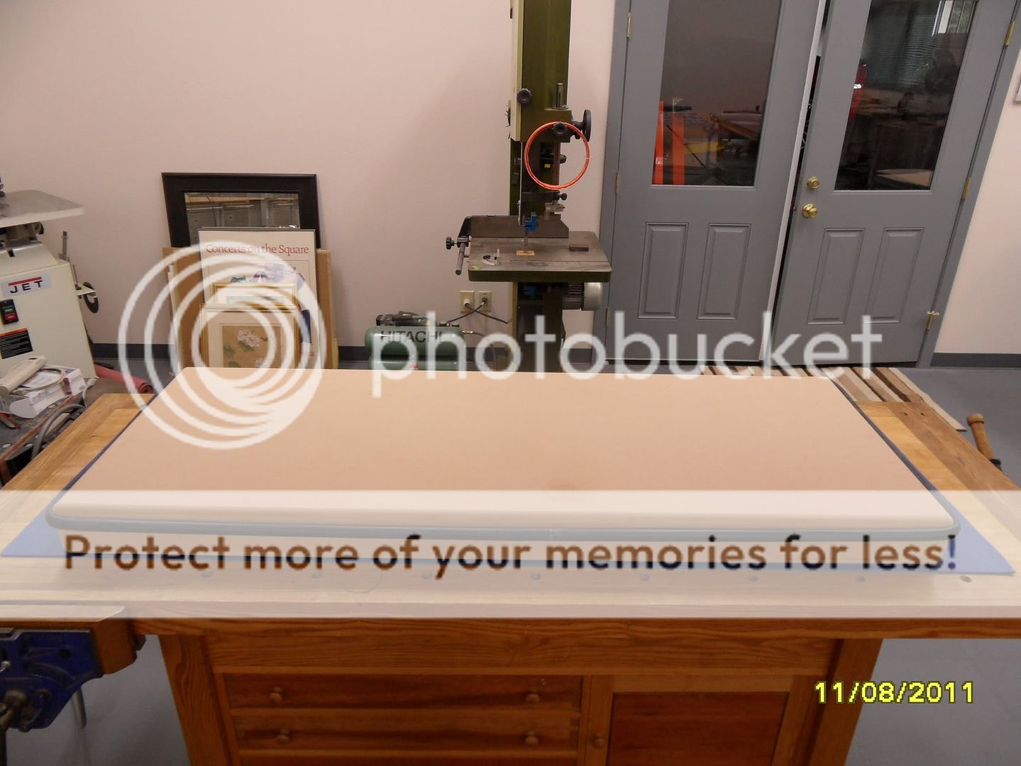
And a picture of the underside:
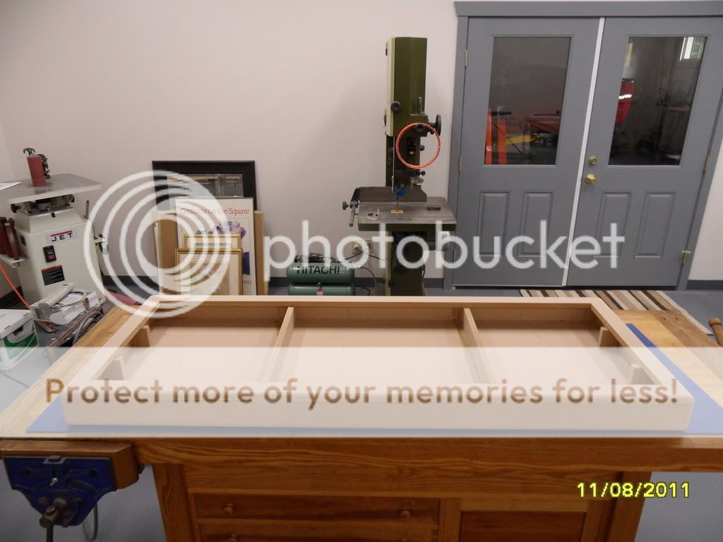
After I build my first panel I'll give the oil burner transformers a try. I have one already that I'll experiment with. The 120 volt side measures about 2.8 ohms andn the 10,000 volt side measures 18,500 ohms. It weighs in at 7 lbs so it has more iron than the toroids. Two of them per side should give me a good step up. Hopefully they will work up to at least 500 hz.Here are some pictures of my stretching table:
And a picture of the underside:


 jer
jer Thanks. I just built the shop and attached 2 car garage. Altogether, 1600 sq ft. divided evenly between the two. The garage is complete with cabinets and car lift, but I'm still working on the wood shop. This Winter I hope to get a good dust collection system installed to cover all the power tools. But first I have to build the electrostatics.
I have tried many, many off the shelf transformers in the past, and I couldn't find any that sounds as good as a pair of custom wound transformers. In Thailand we are still able to get custom wound transformers at reasonable price. If you don't mind the shipping cost, i think it's easier to buy them rather than trials and errors. Let me know if you are interested.
By the way, I run my ESL fullrange.
Wachara C.
By the way, I run my ESL fullrange.
Wachara C.
I don't know much about transformers and hope somebody will address the content of this post because it is inherent in the direction this thread has taken with the last few well-informed posts.
In the old days when tube output transformers were plentiful*, I tried maybe a dozen on ESL panels over a few years. Still have a Thordarson pair in my tweeter system. Dynaco ST70 transformers were popular - I still have a pair and others in my spare parts box. That's what was used at the time. My ear impression and to the poor extent I could measure electric output at the time, was that large variations were present in sound.
How come people are so casual about any kind of transformer-like device (including oil-burner sparkers.... tried one for bias long ago) being pressed into service today? Is it just a matter of windings and iron, along with minor considerations of capacitance, etc. with no concern for frequency response? Will almost any toroid be OK if it has a favourable turns ratio, iron content, and you have faith it can withstand the bias voltage?
Can someone say more about electrical testing, esp. using the panels in the test circuit? What're the test circuits? What kind of freq response should be expected... rising, falling, or flat?
Ben
*last year on eBay, I sold a single beautiful potted Partridge output transformer I had sitting around, the glory of yesteryear, for about $1000. Not bad for something I paid a few bucks for on a Harvey's Radio (NYC) remainder table in 1967.
Last edited:
How come people are so casual about any kind of transformer-like device (including oil-burner sparkers.... tried one for bias long ago) being pressed into service today? Is it just a matter of windings and iron, along with minor considerations of capacitance, etc. with no concern for frequency response? Will almost any toroid be OK if it has a favourable turns ratio, iron content, and you have faith it can withstand the bias voltage?
Hello bentoronto,
Distortion in transformers results from current in the primary not following the voltage applied to the primary. The better the core material, the more closely the current follows the applied voltage. For tube amplifiers, this is very important since the output impedance of the tubes driving the transformers is rather high. The distorted current produces a distorted voltage drop across the output impedance with modulates the voltage reaching the primary winding with a voltage proportional to the distorted current.
In the case of ESL step-up transformers the source impedance is usually quite low, usually defined by the series damping resistance of 1-2 ohms. So, the distorted primary current has little effect on the voltage reaching the primary windings and thus the voltage induced into the secondary.
Use of high quality transformer steel is still advantageous for best core saturation capability, and higher primary inductance with fewer primary turns.
I'm not sure about the oil burner transformers, but most modern toroidal power transformers use fairly good quality grain oriented steel to minimize the amount of copper needed for the windings and thus maximize profit.
For ESL step-up transformers useable bandwidth is defined by:
1) Low frequency limit is defined by power handling capability(ie core saturation).
Bigger core, better quality core material, and more primary turns increases LF power handling capability.
2) High frequency limit is defined by leakage inductance in combination with capacitive load maded up of the winding capacitance + ESL capacitance.
Lower leakage inductance and/or capacitanced extends the HF limit. However, the winding configuration requirements for these two properties conflict with each other, so compromise is required.
Can someone say more about electrical testing, esp. using the panels in the test circuit? What're the test circuits? What kind of freq response should be expected... rising, falling, or flat?
ESL step-up transformers will have a flat response between the LF and HF cut-off points. The behavior of the response at the HF cut-off can be varied from under-damped to over-damped by "tuning" with a series resistance.
See the following post for some examples plots:
http://www.diyaudio.com/forums/planars-exotics/161485-step-up-transformer-design-20.html#post2147513
The resulting acoustic response when this voltage is applied to the stators of an ESL depends, of course, on many factors such as size/shape of the ESL and diaphragm mass.
Last edited:
Bolserst -
Very kind of you to explain it and provide a link as well. Sadly, I am unable to benefit too much from that level of abstraction.
Could anyone please describe a practical DIYer test set-up for evaluating ESL matching transformers. Now, I don't have a voltmeter that works in the kilovolt range or with a giga-ohm input impedance.
Should the drive voltage to an ESL be flat across the frequency band?
Ben
Could anyone please describe a practical DIYer test set-up for evaluating ESL matching transformers. Now, I don't have a voltmeter that works in the kilovolt range or with a giga-ohm input impedance.
What test equipment do you have? digital voltmeter, LCR meter, oscilloscope, signal generator, etc.
A good transformer will produce a flat voltage response on the secondary when driven by a low impedance source.Should the drive voltage to an ESL be flat across the frequency band?
If it doesn't, I wouldn't bother with it.
A flat voltage response fed to a dipole ESL will result in a rising acoustice response.
So, you need to flatten the acoustic response by some means...electrically with series resistance and/or shelving type filters in the primary or secondary circuits, or acoutstically with segmentation.
What test equipment do you have? digital voltmeter, LCR meter, oscilloscope, signal generator, etc.
No LCR meter but all the usual audio meters, SPL/mic, scope, REW software, spectrum analysis software....
- Status
- This old topic is closed. If you want to reopen this topic, contact a moderator using the "Report Post" button.
- Home
- Loudspeakers
- Planars & Exotics
- Some More Questions On ELS Design