

Thank you.
Emits 12 'speaker, RUBANOID and a tape driver.
The remaining speakers are turned off.
Emits 12 'speaker, RUBANOID and a tape driver.
The remaining speakers are turned off.
very great OLEGsan, how big is the membrane wide x height. From which frequency does it play with and what material did you use for the membrane?
Hi CASSINI67.
I described in detail earlier, starting with # 1163.
Paper for pastels 125 g / m.
Starts to operate from 500 Hz (the frequency is cut off only from below)
I described in detail earlier, starting with # 1163.
Paper for pastels 125 g / m.
Starts to operate from 500 Hz (the frequency is cut off only from below)
So, some time spend with ruba's again 🙂 i try to leave the 20Khz extension as is, and not hunt it for ever. im just gone focus on the other stuff that i want to do better 🙂
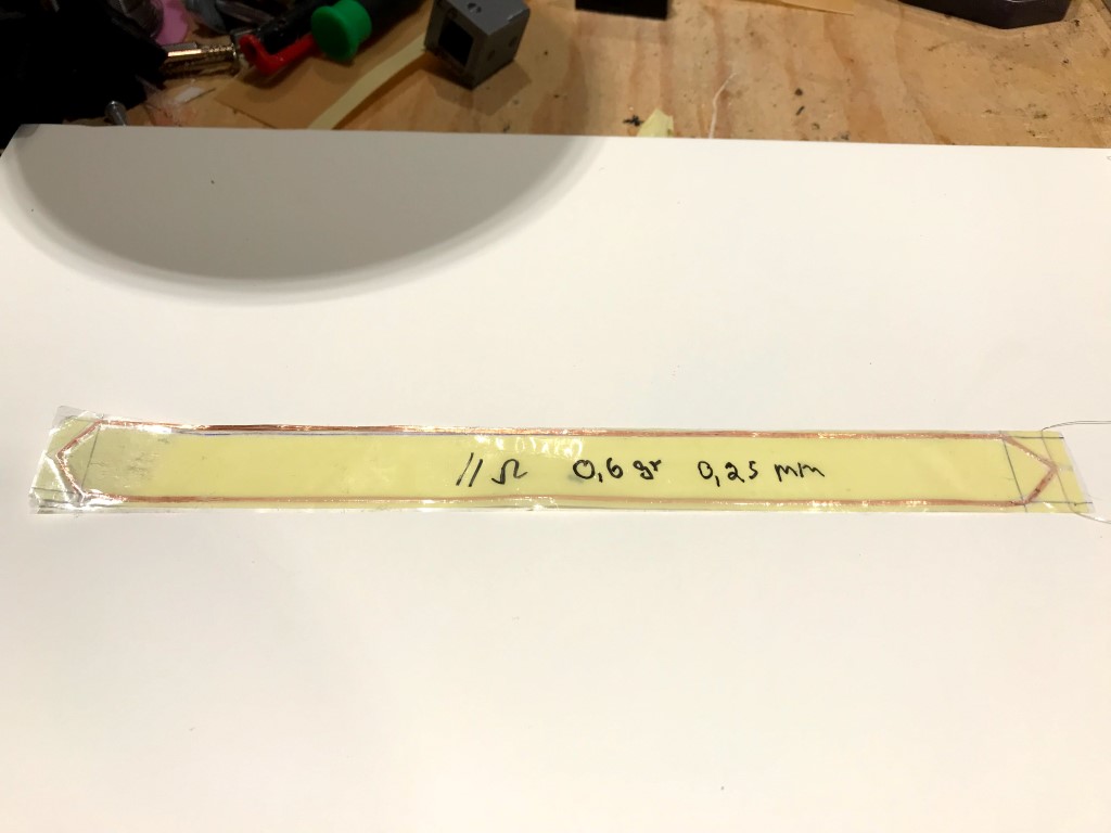
So first thing the coil. i etched and printed and even plotted some coils. but i think wire is the way to go in terms of amount of coil you can stick in there. the more winding the more efficient , maybe even possible to balance high and low end by using dual coils ? so i started wounding again.
First coils and jigs i made ended in the bin 🙂 this is the first one that gives me rather ok results. also i changed some stuff so i could wind and glue the coil to the coil former (nomex) in one go 🙂 although i do need an accelerator for the super glue since the very thin one does not dry quick if you use enough to soak the coil
here some pics
Attachments


i Am using alumnium wire to keep weight down. first pic is a 12 turn coil the middle picture is a 24 turn or twice 12 dual coil actually 🙂
Hi Wrine , Sergiu and all , long time no see but looks like i'm back 😉
Sure it's the first thing we believe about the coil the more turns higher the strength but ...
the more turns ,higher the inductance : not good for upper frequencies
and smaller the wire ,so higher the ohmic resistance not best conditions for efficiency...
so where is the best compromis? Before the printed coil i actually use i tryed several copper windings with someting like 40 turns and more and could'nt have higher upper frequ. response nor better efficiency, may be aluminium could be better ...
Anyway i can't wait for your results and measurements Wrine.
"So first thing the coil. i etched and printed and even plotted some coils. but i think wire is the way to go in terms of amount of coil you can stick in there. the more winding the more efficient "
Sure it's the first thing we believe about the coil the more turns higher the strength but ...
the more turns ,higher the inductance : not good for upper frequencies
and smaller the wire ,so higher the ohmic resistance not best conditions for efficiency...
so where is the best compromis? Before the printed coil i actually use i tryed several copper windings with someting like 40 turns and more and could'nt have higher upper frequ. response nor better efficiency, may be aluminium could be better ...
Anyway i can't wait for your results and measurements Wrine.
Hi Wrine , Sergiu and all , long time no see but looks like i'm back 😉
Sure it's the first thing we believe about the coil the more turns higher the strength but ...
the more turns ,higher the inductance : not good for upper frequencies
and smaller the wire ,so higher the ohmic resistance not best conditions for efficiency...
so where is the best compromis? Before the printed coil i actually use i tryed several copper windings with someting like 40 turns and more and could'nt have higher upper frequ. response nor better efficiency, may be aluminium could be better ...
Anyway i can't wait for your results and measurements Wrine.
Copper is a no go anyways 🙂 inductance might not be that big of a deal, i dont use more then 12 turns or so.
But i noticed it all sucks anyways... 🙁 either coil or flat etched. there are 2 things that always bug me. high freq extend and distortion in lower end.
im not sure but, it seems that 120 grams is the max to get a bit above 15Khz. but 120 grams is floppy as... so you need to go either large or... well it wont work. termination of the paper is a major thing to i see everyone just clamp it but, i can assure you you get massive distortion depending on the size at a frequencies. i had 2 rubas small and larger. they both have this distortion the smaller one higher up in the band vs the bigger one. when terminated softly by 2 pieces of Gaffer tape for instance you can get rid of 70% of that distortion. so instead of clamping the paper straight to the frame get something soft that absorbs the resonance before it gets clamped.
Then again although i did not want to hunt for 20Khz to long, it is still bothering me. with 160 Grams it reaches 12 Khz ~ with 120 a bit higher but mostly the curve you see above that is due some breakup since there is a huge dip before that then a huge peak. breakup or the fact it is emitting high frequencies in the forward direction so the back part of the paper is emitting out of phase with a peace of the front lobbe. making the cylinders less round and more like a butterfly/flat will smooth out the top end a bit. but at the cost of distortion in the mid range..... i did not manage but im rather sure making sure only a few mm emit top end then use thicker paper would resolve this. but using thicker paper hurts efficiency to.
another thing i noticed is that the coil former weight does influence top end. but not so much as the first few mm of the paper after the glued part. adding holes and such in the coil former does hardly anything
I have for instance a coil former made of Carbon weighing the same amount as 2 pieces of 160 grams paper. but since i added a piece of nomex 0.13 mm on the edge of the coil former and then the thicker paper with leaving few mm bare nomex (5mm) it still reaches 18Khz. something i cant get with a version with only 160 grams paper.
Then another thing, going from the original 4 cylinders to 2 , does not change anything, except that the 2 cylinder design goes lower. does not have the out of phase dip from the backside. and is lighter and thus reaches a bit higher.
The the final nail in the coffin (for now) 🙂 is that dispersion is completely random. measure up front, then measure 20 cm to either left or right. and you will see peaks disappear or appear. i recon it is still because the large surface area that emits high frequencies (not left right top bot, but forwards and backwards)
so i had a fast go at it again, but i get sick of the complete randomness of these things. there almost impossible to build the same repeatable. since the bulge it self dictates allot, tension on strings, glue lines etc. that even while using CNC equipment to draw all the stuff i need to cut with etched coils with rather high accuracy, and cncéd frames.
i bet i will get back to it when i got maybe a new idea. but for now. its a typical no free lunch thing. either good high end and crappy midrange or the other way around. or go insane large.... which in my optics beats the purpose since there are many designs that work well when you make them large.
aaah well who knows 🙂
i Am using alumnium wire to keep weight down. first pic is a 12 turn coil the middle picture is a 24 turn or twice 12 dual coil actually 🙂
Hello my friend,
I would not use wire ever if i had to redo this speaker again. If i remember well my biggest diy cutted coil in terms of turns is a fat 1:1 (coil vs gap) and six turns per arm of the coil, wich did improve but NOT in the SPL sector instead in lower frequencies (the ruba could go as low as near 100hz). I dont see any advantage in going too low with this speaker because i have observed that when the membrane moves too much the SPL goes down and the distorsion up... i suspect that when the membrane moves too much in the low end sector, somehow stiffens the membrane like in the case you touch it with your fingers thus reducing its SPL in both mids and hights..
As i see it, a really elegant solution to lower the distorsion even more is to find an affordable and very fibrous material for the membrane (as Olegsan discovered, that it preserves the same sound signature but it sounds even clearer). A good example will be cottone paper, rice paper, washy etc.. or mylar, kapton and other industriall grades.
Cheers
Sergiu
Hi Wrine , Sergiu and all , long time no see but looks like i'm back 😉
Sure it's the first thing we believe about the coil the more turns higher the strength but ...
the more turns ,higher the inductance : not good for upper frequencies
and smaller the wire ,so higher the ohmic resistance not best conditions for efficiency...
so where is the best compromis? Before the printed coil i actually use i tryed several copper windings with someting like 40 turns and more and could'nt have higher upper frequ. response nor better efficiency, may be aluminium could be better ...
Anyway i can't wait for your results and measurements Wrine.
Hi Tubegeek,
The best compromise for round wired coils, i think, is to use a square Aluminium wire (instead of round) to increase the contact area between the coil and membrane + allot of cuts in the promiximity of the the coil and inside it+ really gently applied laqueur on a certain portion of the membrane (as i did: see my pics) in a way that it does not penetrate and saturate that particullar portion of the sheet of paper, to extend the active area of the speaker even more, and improve the dispersion (sweet spot).
I still didnt manage to measure my final version of ruban beacause a hardware faillure in my pc and i'm in the process of moving right now.. but i didnt change a thing on my speakers: they have Al diy cutted with 4 turn coils rated at 8 ohms and diy antyhumidity treatment for the membrane and extended sweet spot with laqueur + the cuts... The membrane didnt bended nor deformed, its still straight with no deformations, even in the winter when the humidity is quite high in my house. The speakers are now producing a slightly different sound compared to the first day because i did a little burn in with them (4 hours with the jlh69 amp pumping aprox 5w in both of them in paralell at 4 ohms) when i was out of home.. 🙂 They sound a bit more open now (subjectivelly speaking) but didnt measured the phenomena.. In rest the laqueured portion of the membrane has changed the collor abit because of the laq used.
I dont intend to change a thing on them because they sound gorgeus as they where builded back then, BUT will change the membrane if i can find a more fibrous paper at 120gr/sqm.
Hello my friend,
I would not use wire ever if i had to redo this speaker again. If i remember well my biggest diy cutted coil in terms of turns is a fat 1:1 (coil vs gap) and six turns per arm of the coil, wich did improve but NOT in the SPL sector instead in lower frequencies (the ruba could go as low as near 100hz). I dont see any advantage in going too low with this speaker because i have observed that when the membrane moves too much the SPL goes down and the distorsion up... i suspect that when the membrane moves too much in the low end sector, somehow stiffens the membrane like in the case you touch it with your fingers thus reducing its SPL in both mids and hights..
As i see it, a really elegant solution to lower the distorsion even more is to find an affordable and very fibrous material for the membrane (as Olegsan discovered, that it preserves the same sound signature but it sounds even clearer). A good example will be cottone paper, rice paper, washy etc.. or mylar, kapton and other industriall grades.
Cheers
Sergiu
Hi Serg !well you might not use wire ever. but that might be because it was copper not aluminium. and you dont measure as often , and i did not see many flat pancake coils in this topic 🙁. you dont go 100hz without distortion. i can go as low as 20 if you want.... but at which spl compared to the rest (and with what amount of distortion 🙂 ). thats the question. the reason distortion goes away or less when touching is not the output but dampening. the los of spl is the same reason 🙁 so getting a very fibers paper will screw up you output and the top end. but will dampen the mid/low end 🙂
i once tried washy and rice. and they are useless since it does not give any stiffness./weight. it will be allot of dB down to make them work 🙁 the low end wont work either with such sloppy paper.
Mylar is on the other part of the spectrum in the damping apartment it is really noisy compared to paper. it is really strong but not so stiff and very noisy, Kapton is really sloppy compared to Mylar, it is heavy and gives even less stiffness. just my 2 cents. and i would love people to measure some rubas. since i still did not see a perfect one 🙁 not even from the 70.000 euro costing one 🙂 haha i beginning to doubt if it can be done to begin with 🙁. i hope so 🙂
I aded my answers in your reply my friend to be more accurate.
Copper is a no go anyways 🙂 inductance might not be that big of a deal, i dont use more then 12 turns or so.
But i noticed it all sucks anyways... 🙁 either coil or flat etched. there are 2 things that always bug me. high freq extend and distortion in lower end.
Why go lower then 200-250hz with a speaker that has membranes wich moves when you blow air with your mouth on them?
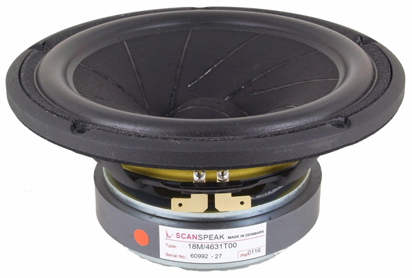
If you want to make a fullranger try tricks from the bigger players in this industry (an ideea) like making a membrane from pieces of paper bonded diagonally like scan speaks speakers, or make trenches or dents with a round finished metall rod template like big headphone speakers have on theyr membrane (only pointed on the outside of the cils) like these little ones have from bellow. The ideea is to make them diagonally so they have effect. Both of these sollutions stiffens the membrane to get what you want my friend.
im not sure but, it seems that 120 grams is the max to get a bit above 15Khz. but 120 grams is floppy as... so you need to go either large or... well it wont work.
Then try to stiffen it like i showed you earlyier.
termination of the paper is a major thing to i see everyone just clamp it but, i can assure you you get massive distortion depending on the size at a frequencies. i had 2 rubas small and larger. they both have this distortion the smaller one higher up in the band vs the bigger one. when terminated softly by 2 pieces of Gaffer tape for instance you can get rid of 70% of that distortion. so instead of clamping the paper straight to the frame get something soft that absorbs the resonance before it gets clamped.
Well i have readed this info (not to clamp the paper directly to the frame) from the patents so i have used something like the gaffer tape ( a thicker very soft rubberized sponge like stuff used for exterior doors sealing) from the begining but didnt think that it will lower the distorsion that much.... nice findings my friend.
Then again although i did not want to hunt for 20Khz to long, it is still bothering me. with 160 Grams it reaches 12 Khz ~ with 120 a bit higher but mostly the curve you see above that is due some breakup since there is a huge dip before that then a huge peak. breakup or the fact it is emitting high frequencies in the forward direction so the back part of the paper is emitting out of phase with a peace of the front lobbe. making the cylinders less round and more like a butterfly/flat will smooth out the top end a bit. but at the cost of distortion in the mid range.....
I found simillar things with the butterfly shape but wasnt shure about the distorsion figures. Also the butterfly shape does make the sound abit restrained like in the case when you tension the elastics a bit more than needed.
i did not manage but im rather sure making sure only a few mm emit top end then use thicker paper would resolve this. but using thicker paper hurts efficiency to.
That's right and you can add a very small sweet spot here too.
another thing i noticed is that the coil former weight does influence top end. but not so much as the first few mm of the paper after the glued part. adding holes and such in the coil former does hardly anything
It may influence abit less the top end but you gain lower overall mass and the space near the coil will have lower mass wich will improve other aspects like more sensitivity in the upper fequencies and mids and improve the ability of the membrane to start and stop reproducing a particullar frequency range faster and respond faster.
I have for instance a coil former made of Carbon weighing the same amount as 2 pieces of 160 grams paper. but since i added a piece of nomex 0.13 mm on the edge of the coil former and then the thicker paper with leaving few mm bare nomex (5mm) it still reaches 18Khz. something i cant get with a version with only 160 grams paper.
Why dont you try even roughlly to apply what hard laq you have at you disposall on the membrane, horizontally, comming from the coil former or coil to the half membrane (on the exterior of the cilinders) when the ruba is allready made, or split the membrane in four parts like 1/4 (quarter) naked paper then 1/4+1/4 laq then the other 1/4 naked paper (no laq) before sticking or cutting the coil turns? Then let it dry for good (1-2 days), and then compare to the othr versions with no laq.
Then another thing, going from the original 4 cylinders to 2 , does not change anything, except that the 2 cylinder design goes lower. does not have the out of phase dip from the backside. and is lighter and thus reaches a bit higher.
I didnt experiment on this but happy that you and others tried and shared with me and other interested people.
The the final nail in the coffin (for now) 🙂 is that dispersion is completely random. measure up front, then measure 20 cm to either left or right. and you will see peaks disappear or appear. i recon it is still because the large surface area that emits high frequencies (not left right top bot, but forwards and backwards)
Same here, but with extreme care and almost a week to make two complete membranes for a stereo pair you can make them almost the same (left to right channel) and simillar to the other versions (that's how good it can get in a diy home made manner and tons of hard work and tons of faillures from wich i remained with very few paper reserve for future tests); the most annoying part is with the tension from the elastics to get things right and one of the most important aspects is the centering in the gap, wich, if not done proprelly it can ruin everithing (believe me). To be honest, i remade the centering three times to get a proper centering, this way: first center and tension the elastics harder than it should, than let it this way for 1 week so that the cills gain the cillindricall shape for a lifetime + force the coil to stay still and straight vertically, then, after a week diassembly everything, let the membrane loosen outside the gap for a day and observe from the top if its round without creases or bumps (everything should be ok if well centered and alligned from ghe first time) and if everything is ok (if everything is bonded well, observe the coil, etc), then recenter gently and more accurate the coil and put everything back together, then let it for another week, and then cut the elastics to see (observe) if the coil sustains itself alone in the gap without friction, if so, then put the finall ellastics in and adjust and tension carefully and center acuratelly and then voilla, if not, redo the last step and readjust from the whole assembly ( edges of the cils and from the shape and from the coil area deforming a bit the cils till they get a shape between ovall and round) WITH the membrane still in place and loosening it from the verticall square Al pipes then add elastics and then step three again till its good.
Then if all its good burn in as long as you can, then center again if its the case and retension (if its the case but it shouldnt be) and THEN voilla...🙂) 😡
😡

It will take about another 3-4 weeks to fine tune after the week needed for the assembly of the coil and membrane and then at last, i had a proper listening session.. 😎🙄 This was my way of doing this speaker.
so i had a fast go at it again, but i get sick of the complete randomness of these things. there almost impossible to build the same repeatable. since the bulge it self dictates allot, tension on strings, glue lines etc. that even while using CNC equipment to draw all the stuff i need to cut with etched coils with rather high accuracy, and cncéd frames.
i bet i will get back to it when i got maybe a new idea. but for now. its a typical no free lunch thing. either good high end and crappy midrange or the other way around. or go insane large.... which in my optics beats the purpose since there are many designs that work well when you make them large.
aaah well who knows 🙂
I suggest you should not go fullrange (you will be dissapointed again and again and again as i did..) 🙂
Cheers
Sergiu
Copper is a no go anyways 🙂 inductance might not be that big of a deal, i dont use more then 12 turns or so.
But i noticed it all sucks anyways... 🙁 either coil or flat etched. there are 2 things that always bug me. high freq extend and distortion in lower end.
Why go lower then 200-250hz with a speaker that has membranes wich moves when you blow air with your mouth on them?
If you want to make a fullranger try tricks from the bigger players in this industry (an ideea) like making a membrane from pieces of paper bonded diagonally like scan speaks speakers, or make trenches or dents with a round finished metall rod template like big headphone speakers have on theyr membrane (only pointed on the outside of the cils) like these little ones have from bellow. The ideea is to make them diagonally so they have effect. Both of these sollutions stiffens the membrane to get what you want my friend.
An externally hosted image should be here but it was not working when we last tested it.
im not sure but, it seems that 120 grams is the max to get a bit above 15Khz. but 120 grams is floppy as... so you need to go either large or... well it wont work.
Then try to stiffen it like i showed you earlyier.
termination of the paper is a major thing to i see everyone just clamp it but, i can assure you you get massive distortion depending on the size at a frequencies. i had 2 rubas small and larger. they both have this distortion the smaller one higher up in the band vs the bigger one. when terminated softly by 2 pieces of Gaffer tape for instance you can get rid of 70% of that distortion. so instead of clamping the paper straight to the frame get something soft that absorbs the resonance before it gets clamped.
Well i have readed this info (not to clamp the paper directly to the frame) from the patents so i have used something like the gaffer tape ( a thicker very soft rubberized sponge like stuff used for exterior doors sealing) from the begining but didnt think that it will lower the distorsion that much.... nice findings my friend.
Then again although i did not want to hunt for 20Khz to long, it is still bothering me. with 160 Grams it reaches 12 Khz ~ with 120 a bit higher but mostly the curve you see above that is due some breakup since there is a huge dip before that then a huge peak. breakup or the fact it is emitting high frequencies in the forward direction so the back part of the paper is emitting out of phase with a peace of the front lobbe. making the cylinders less round and more like a butterfly/flat will smooth out the top end a bit. but at the cost of distortion in the mid range.....
I found simillar things with the butterfly shape but wasnt shure about the distorsion figures. Also the butterfly shape does make the sound abit restrained like in the case when you tension the elastics a bit more than needed.
i did not manage but im rather sure making sure only a few mm emit top end then use thicker paper would resolve this. but using thicker paper hurts efficiency to.
That's right and you can add a very small sweet spot here too.
another thing i noticed is that the coil former weight does influence top end. but not so much as the first few mm of the paper after the glued part. adding holes and such in the coil former does hardly anything
It may influence abit less the top end but you gain lower overall mass and the space near the coil will have lower mass wich will improve other aspects like more sensitivity in the upper fequencies and mids and improve the ability of the membrane to start and stop reproducing a particullar frequency range faster and respond faster.
I have for instance a coil former made of Carbon weighing the same amount as 2 pieces of 160 grams paper. but since i added a piece of nomex 0.13 mm on the edge of the coil former and then the thicker paper with leaving few mm bare nomex (5mm) it still reaches 18Khz. something i cant get with a version with only 160 grams paper.
Why dont you try even roughlly to apply what hard laq you have at you disposall on the membrane, horizontally, comming from the coil former or coil to the half membrane (on the exterior of the cilinders) when the ruba is allready made, or split the membrane in four parts like 1/4 (quarter) naked paper then 1/4+1/4 laq then the other 1/4 naked paper (no laq) before sticking or cutting the coil turns? Then let it dry for good (1-2 days), and then compare to the othr versions with no laq.
Then another thing, going from the original 4 cylinders to 2 , does not change anything, except that the 2 cylinder design goes lower. does not have the out of phase dip from the backside. and is lighter and thus reaches a bit higher.
I didnt experiment on this but happy that you and others tried and shared with me and other interested people.
The the final nail in the coffin (for now) 🙂 is that dispersion is completely random. measure up front, then measure 20 cm to either left or right. and you will see peaks disappear or appear. i recon it is still because the large surface area that emits high frequencies (not left right top bot, but forwards and backwards)
Same here, but with extreme care and almost a week to make two complete membranes for a stereo pair you can make them almost the same (left to right channel) and simillar to the other versions (that's how good it can get in a diy home made manner and tons of hard work and tons of faillures from wich i remained with very few paper reserve for future tests); the most annoying part is with the tension from the elastics to get things right and one of the most important aspects is the centering in the gap, wich, if not done proprelly it can ruin everithing (believe me). To be honest, i remade the centering three times to get a proper centering, this way: first center and tension the elastics harder than it should, than let it this way for 1 week so that the cills gain the cillindricall shape for a lifetime + force the coil to stay still and straight vertically, then, after a week diassembly everything, let the membrane loosen outside the gap for a day and observe from the top if its round without creases or bumps (everything should be ok if well centered and alligned from ghe first time) and if everything is ok (if everything is bonded well, observe the coil, etc), then recenter gently and more accurate the coil and put everything back together, then let it for another week, and then cut the elastics to see (observe) if the coil sustains itself alone in the gap without friction, if so, then put the finall ellastics in and adjust and tension carefully and center acuratelly and then voilla, if not, redo the last step and readjust from the whole assembly ( edges of the cils and from the shape and from the coil area deforming a bit the cils till they get a shape between ovall and round) WITH the membrane still in place and loosening it from the verticall square Al pipes then add elastics and then step three again till its good.
Then if all its good burn in as long as you can, then center again if its the case and retension (if its the case but it shouldnt be) and THEN voilla...🙂)
😡 It will take about another 3-4 weeks to fine tune after the week needed for the assembly of the coil and membrane and then at last, i had a proper listening session.. 😎🙄 This was my way of doing this speaker.
so i had a fast go at it again, but i get sick of the complete randomness of these things. there almost impossible to build the same repeatable. since the bulge it self dictates allot, tension on strings, glue lines etc. that even while using CNC equipment to draw all the stuff i need to cut with etched coils with rather high accuracy, and cncéd frames.
i bet i will get back to it when i got maybe a new idea. but for now. its a typical no free lunch thing. either good high end and crappy midrange or the other way around. or go insane large.... which in my optics beats the purpose since there are many designs that work well when you make them large.
aaah well who knows 🙂
I suggest you should not go fullrange (you will be dissapointed again and again and again as i did..) 🙂
Cheers
Sergiu
Hi Serg !well you might not use wire ever. but that might be because it was copper not aluminium. and you dont measure as often , and i did not see many flat pancake coils in this topic 🙁. you dont go 100hz without distortion. i can go as low as 20 if you want.... but at which spl compared to the rest (and with what amount of distortion 🙂 ). thats the question. the reason distortion goes away or less when touching is not the output but dampening. the los of spl is the same reason 🙁 so getting a very fibers paper will screw up you output and the top end. but will dampen the mid/low end 🙂
i once tried washy and rice. and they are useless since it does not give any stiffness./weight. it will be allot of dB down to make them work 🙁 the low end wont work either with such sloppy paper.
Mylar is on the other part of the spectrum in the damping apartment it is really noisy compared to paper. it is really strong but not so stiff and very noisy, Kapton is really sloppy compared to Mylar, it is heavy and gives even less stiffness. just my 2 cents. and i would love people to measure some rubas. since i still did not see a perfect one 🙁 not even from the 70.000 euro costing one 🙂 haha i beginning to doubt if it can be done to begin with 🙁. i hope so 🙂
Indeed I didnt measure it yet but will. But i dont expect a +-1dB freq response or 0.1% dist from an 1/2m long allmost fullrange speaker. I'm after its subjective qualityies; Feastrex, Fostex and others dont aim for that too and they have smaller speakers than this one (ruba) and are really prized speakers subjectivelly speaking, even by Nelson Pass itself.
I dont have a studio to make recordings so to aim for sub 1% dist is not a must for me. I dont perceive, subjectivelly speaking, any peaks or distorsion comming from the speaker itself but from the room. My room is reflecting peaks all over the place if I go louder than aprox 8-10w (wich is prety darn loud in my opinion). This is what I can say for shure because I measured it and its also because its untreated...
I just love to listen to live music and to really feel what the singer wanted to transmit through its songs and this speaker really takes me there .
The rubas are not wraped for packing yet so I hope to measure them, but I dont expect sy-fy figures from it... 🙂
I am curious too if someone on this planet can really measure high end scores from this speaker.
I believe that the dims of 25, 15 and 10cm are the optimum dims for getting decent measured results as Linaeum did, no more no less, but at a cost in therms of other aspects...
Last edited:
Indeed I didnt measure it yet but will. But i dont expect a +-1dB freq response or 0.1% dist from an 1/2m long allmost fullrange speaker. I'm after its subjective qualityies; Feastrex, Fostex and others dont aim for that too and they have smaller speakers than this one (ruba) and are really prized speakers subjectivelly speaking, even by Nelson Pass itself.
I dont have a studio to make recordings so to aim for sub 1% dist is not a must for me. I dont perceive, subjectivelly speaking, any peaks or distorsion comming from the speaker itself but from the room. My room is reflecting peaks all over the place if I go louder than aprox 8-10w (wich is prety darn loud in my opinion). This is what I can say for shure because I measured it and its also because its untreated...
I just love to listen to live music and to really feel what the singer wanted to transmit through its songs and this speaker really takes me there .
The rubas are not wraped for packing yet so I hope to measure them, but I dont expect sy-fy figures from it... 🙂
I am curious too if someone on this planet can really measure high end scores from this speaker.
I believe that the dims of 25, 15 and 10cm are the optimum dims for getting decent measured results as Linaeum did, no more no less, but at a cost in therms of other aspects...
well yeah they can perform rather well in the distortion range. but not so much in the flatness range i believe 🙂 the claims of the french dude , for instance im pretty sure never going to be reached. < 1% 105 db etc 🙂 not so sure 🙂 but the differentiation in response is for sure peaking more then 10 dB. do they sound nice, yes they can sound nice and well.... different 🙂
Serg i tried lacquer dents and all sorts 🙂 im not so much looking for full range. i am looking for 300hz and up. without having to use 200 euro of magnets and potential a crushed finger 🙂. the thing is when i smack 200 euro on magnets for something, there are suddenly allot of options to trow 200 at 🙂 that work well if you want to go that route 🙂 without weird top end 🙂 aah well i think they are really cool, but not perfect as of yet. i think we and maybe others dont quite made the perfect one yet. (if possible) but a guy can only take so many failures 😉 haha my room is littered with membranes 🙂 i did not found my holy grail as of yet 🙂
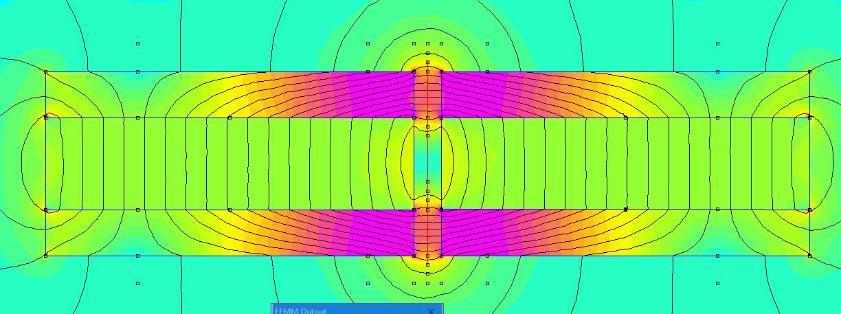
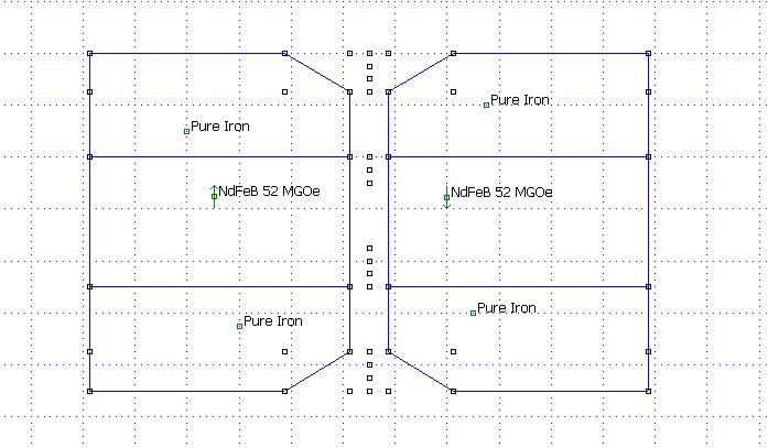
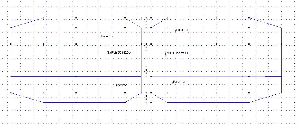
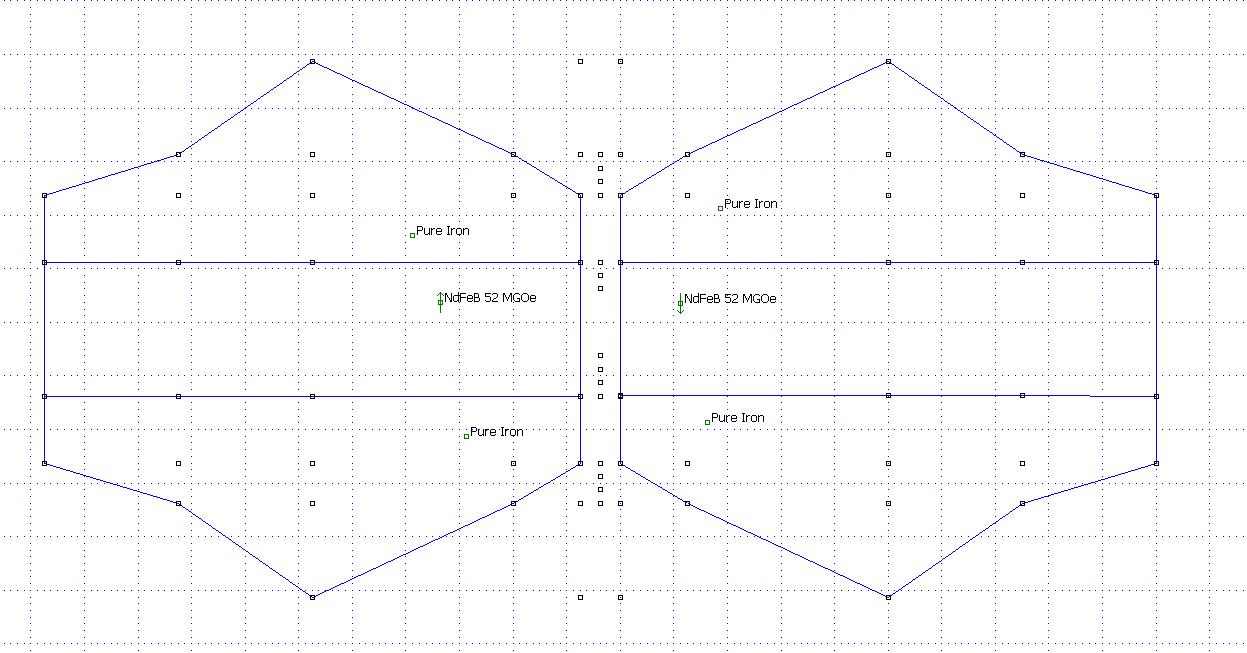
If I have understand you correctly, your motor looks like this from the top:
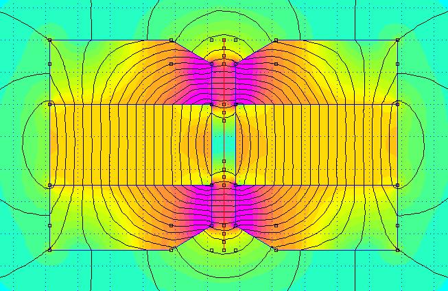
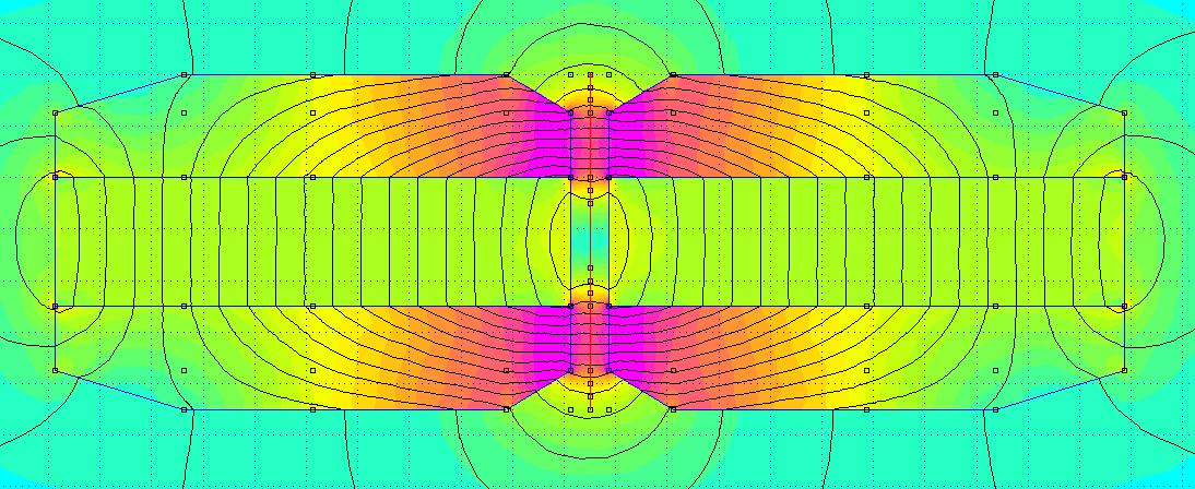
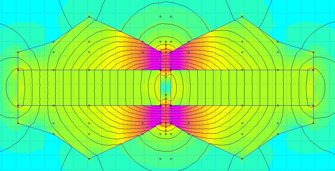
Simulation:

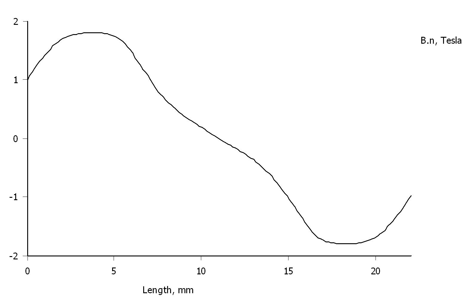
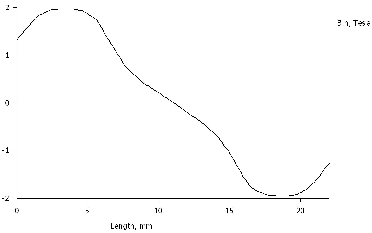
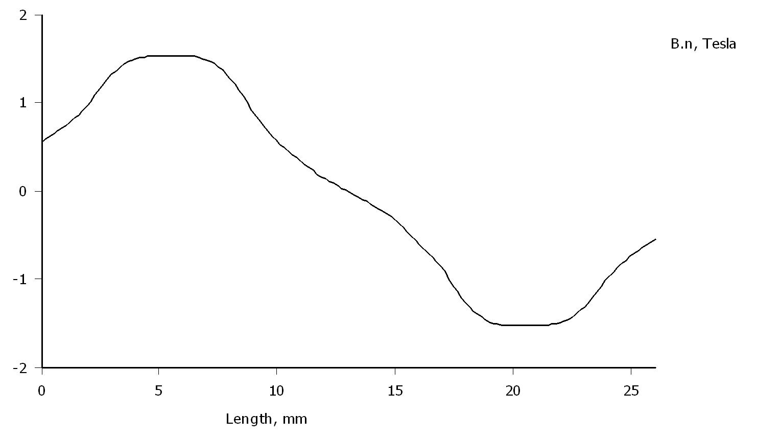
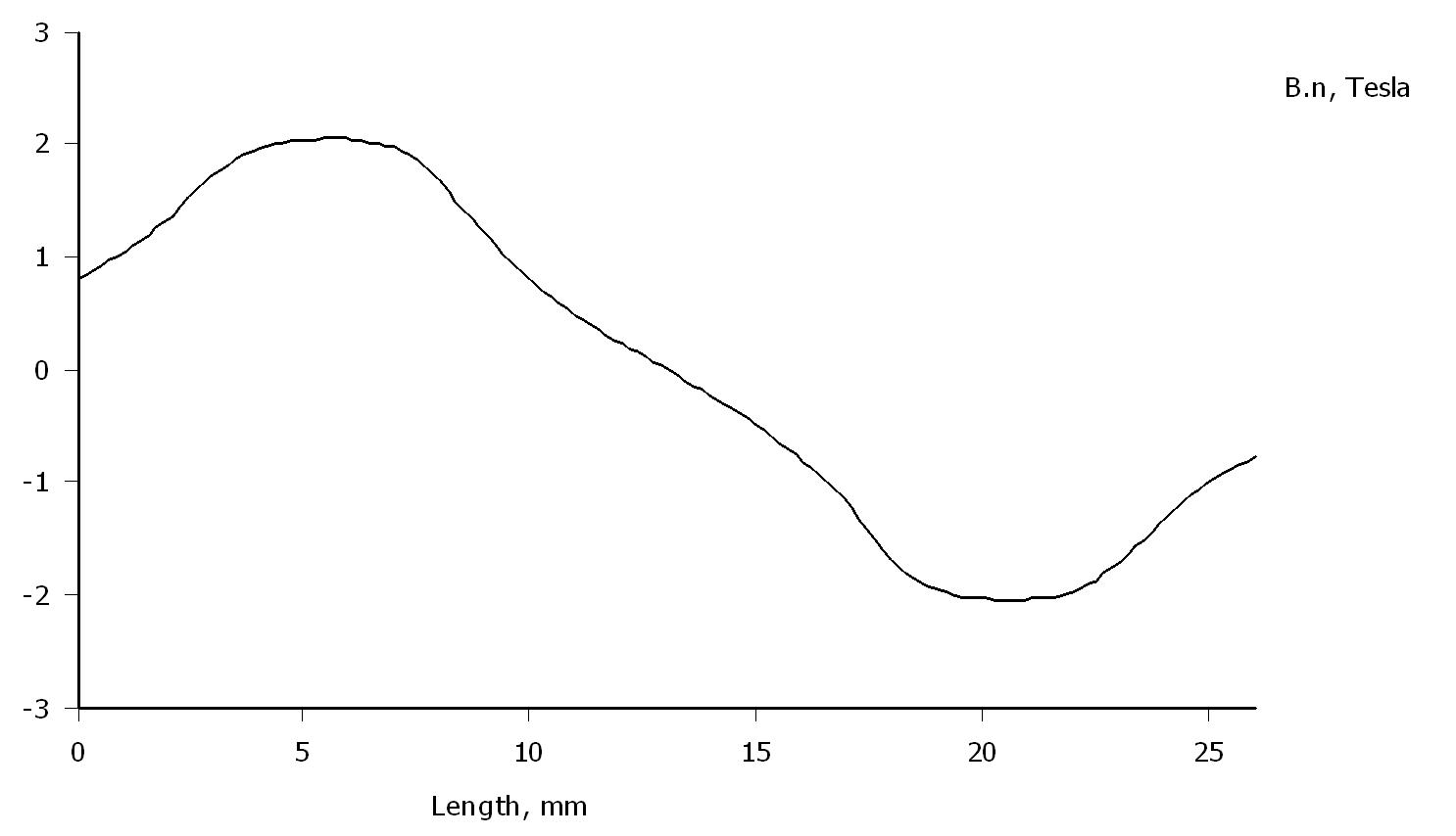
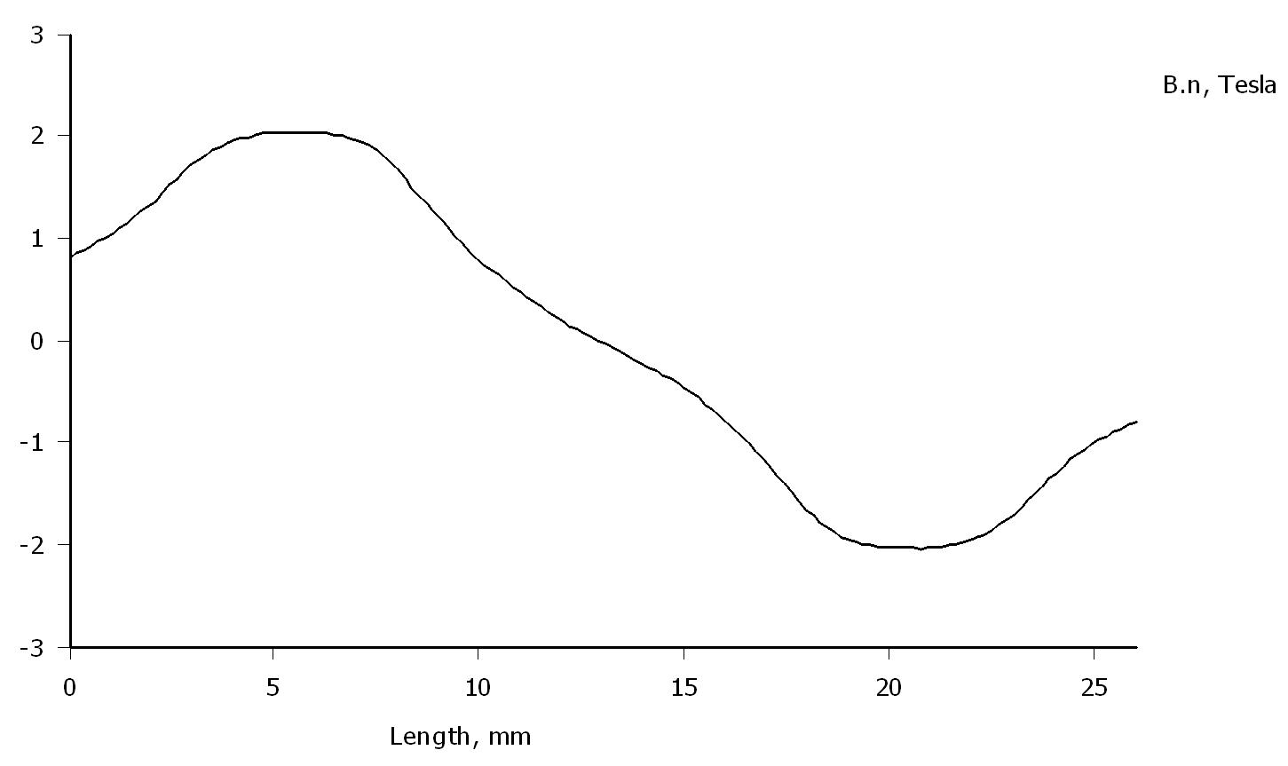
Flux in the gap:
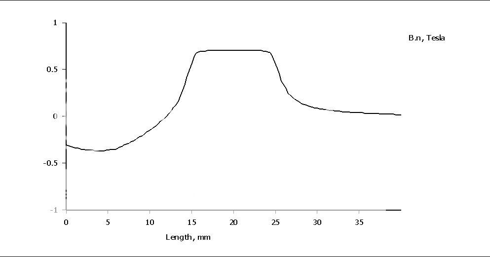
Fairly strong flux density but the direction flips if the coil is outside the gap.
Hello,
I have a question for the magnet specialist : i have understood that we are trying to get maximum possible flux between the soft iron bar. But the question is : should we have the lowest possible flux between the magnets ?
I mean, we have a sandwich of soft iron/magnet/soft iron. We are searching for the maximum flux between the 2 plates of soft iron because it is where the coil will be. But do we search the minimum possible between the magnets or also the maximum possible ?
Thank you for your help !
I am trying to figure out how to maximize. I have bought N52 magnets 50x20x10. And soft steel 25x15. I have a miller so a lot of configurations are possible.
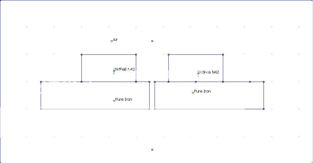
Not directly an answer to your question, but this is how my simple Rubanoid motor looks like with a 3 mm gap:
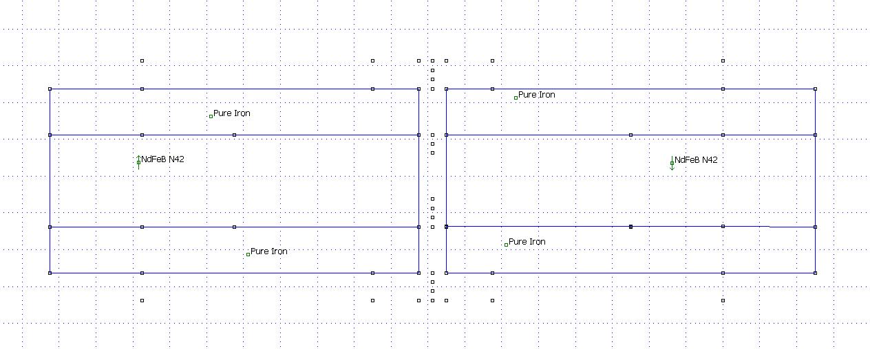
And a more complicated one:
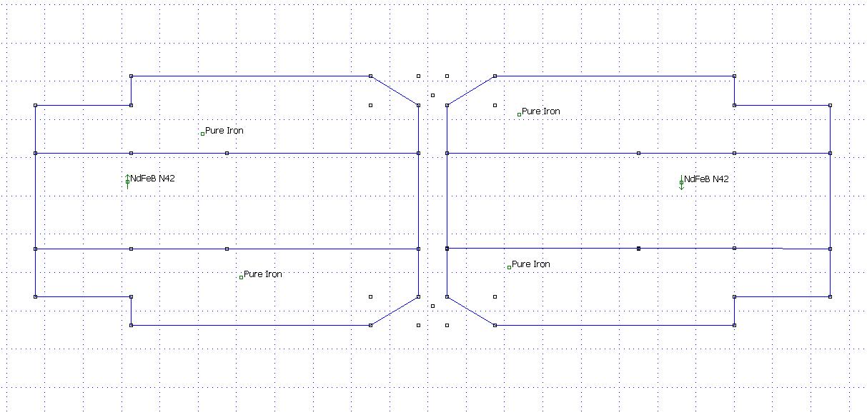
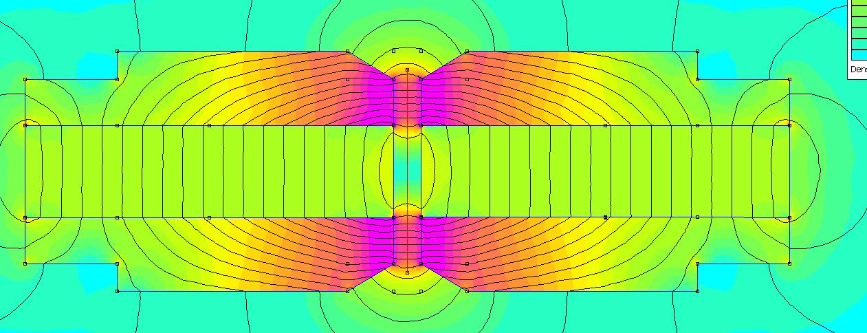
The magnets are N42 40x20x10 mm.
As you see, I have found that there's nothing to gain by letting the iron "over hang" the magnetes.
So in your case the iron should be 20 mm (or 50 mm if your mount the magnets the way I do).
The coil would look something like this:
The coil is underhunged, so the coil must be mounted with great precision to get a reasonable Xmax.
I will try to do some simulations on your hardware.
How shall the magnets be oriented, 20 or 50 mm?
And a more complicated one:
The magnets are N42 40x20x10 mm.
As you see, I have found that there's nothing to gain by letting the iron "over hang" the magnetes.
So in your case the iron should be 20 mm (or 50 mm if your mount the magnets the way I do).
The coil would look something like this:
The coil is underhunged, so the coil must be mounted with great precision to get a reasonable Xmax.
I will try to do some simulations on your hardware.
How shall the magnets be oriented, 20 or 50 mm?
Last edited:
Suggestion for motor with a 20 mm orientation of magnets:
50 mm orientation.
This is how strong you can get!
An externally hosted image should be here but it was not working when we last tested it.
An externally hosted image should be here but it was not working when we last tested it.
An externally hosted image should be here but it was not working when we last tested it.
50 mm orientation.
An externally hosted image should be here but it was not working when we last tested it.
An externally hosted image should be here but it was not working when we last tested it.
An externally hosted image should be here but it was not working when we last tested it.
This is how strong you can get!
Well, just for the fun of it:
But the plot was the same as above:
Even it can be tweaked to a higher or wider field, I guess it isn't worth the effort neither design nor build wise.
An externally hosted image should be here but it was not working when we last tested it.
An externally hosted image should be here but it was not working when we last tested it.
But the plot was the same as above:
An externally hosted image should be here but it was not working when we last tested it.
Even it can be tweaked to a higher or wider field, I guess it isn't worth the effort neither design nor build wise.
- Home
- Loudspeakers
- Planars & Exotics
- A DIY Ribbon Speaker of a different Kind