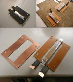
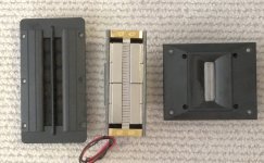
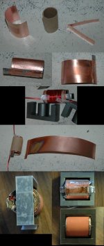
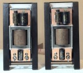
Here is info on the tweeter I made. It has 4 5/16 inch long magnetic part and ribbon is 3/8 inch wide. .03 ohms for pleated ribbon. This is quite a project to make the parts. A lot of cutting, filing, drilling, and tapping. The 1/2 X 1/2 X 2 inch magnets are the N52 which is the strongest I could find. Since it is high current, the wires are large and soldered into deep holes in the brass part. Top part is thick so will press on ribbon evenly. One end is insulated from steel part. When done and has a good ribbon, will have an aluminum screen cover. So far testing things, I have destroyed 3 ribbons. One to measure the resistance, one when I hooked it to transformer at full volume, that was ear splitting! One jusr wasn't right, so rubbed. Hard to get one straight. I don't know if kitchen foil is really any good for this. Seems stuff a little tempered would work better.
Attachments
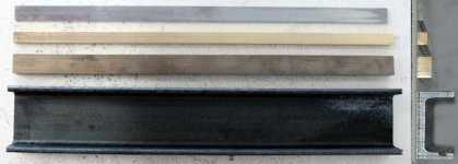
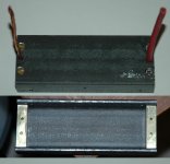
I don't know if kitchen foil is really any good for this. Seems stuff a little tempered would work better.
Heavy Metal!
Monster Magnets!
You da'MAN!
Here is what I have learned:
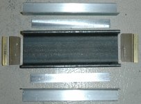
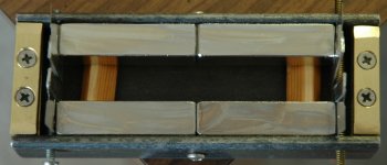
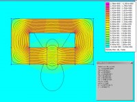
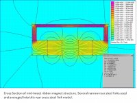
1) Your ribbon has extra pole metal that will hurt efficiency. Steel/Iron saturates ~ 1.5Tesla, so the highest gap flux comes from having just the monster NdFeB magnets next to the ribbon in the gap, and attached directly to the large steel/iron pole pieces, held with either super-duper glue or AL-sheet clamps. Putting steel/iron poles next to the ribbon will reduce the max Telsa flux when super magnets are used.
2) For the optimum uniform gap magnetic field, you either want to use non-magnetic spacer(ribbon_clamp) materials like aluminum, or put several thin steel/iron spacers at the top, bottom, 0.25x, 0.5x, 0.75x positions. The steel spacers can be thin but deep for extra volume.
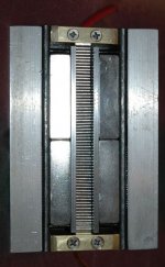
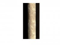
3) Household AL-foil is typically between 12.5u and 25u-meters thick. Any pure Al true-ribbon foil above ~6 microns "sizzles" to my ears when used in a tweeter. My tweeters use 5.4um pure aluminum foil, and this thickness is soft enough to dampen any "sizzle". SHAKE-SHAKE-SHAKE your ribbon AL foil and listen for "sizzle". Some very thin AL-ribbon tweeters, like the 2um Magnepan, use AL Alloy 5056 for higher strength and 2x higher resistance/square. High failure rates are common with <5um AL foil.
4) Several modern tweeters like the RAAL "emboss" the AL foil instead of corrugating it. This both reduces the weight, and keeps the ribbon motion more planar with just suspension at the ends. RAAL uses heat-shrink mylar at the top-bottom of the embossed ribbon attachment as a suspension. RAAL keeps the ribbon height to a minumum by using the thin PCB copper for the ribbon attachment.
5) There are a few very good threads on multi-filiment wire step-up transformer winding. Toroid, and stacked-foil C_cores from AMCC are often used.
6) A ribbon is very sonically-transparent of any rear reflections, so extensive rear dampening material (wool, fiberglass) is often used behind monpole ribbons.
Attachments
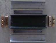
So, I should remove the iron parts, and make a wider ribbon. Ideally, replace the magnets with ones 1/2 X 5/8 inch and use the same size ribbon. They are so strong, no glue needed, just brass pegs in the iron so they don't tend to go all the way to the back.
I have a way to emboss it, so will try that also. I prefer the end clamps for the ribbon. harder to make, but very easy to replace a ruined ribbon.
One of the threads is mine on transformer winding. I have been doing it for 40 years, so know how to wind all kinds. For this I found that Ferrite is the only good core, the rest are too expensive for me to try, or are just too lossy. For this, RF type transformer works best. Basically flattened tube with the primary inside.
Yes, I was going to put dampening stuff in it when completed.
MAXIMUM FLUX: For a monopole ribbon tweeter the commercially successful RAAL uses a 3-sided fully enclosed steel magnetic circuit to get the highest flux in the gap. Extensive absorption material and clever partitioning of the cavity to shorter than a wavelength widths are necessary to reduce resonances and rear ribbon reflections. To get the maximum gap flux some DIY'ers go so far as to use 1" x 3" steel for the sides and rear - very heavy metal.
MINIMUM REAR CAVITY EFFECTS: To minimize rear cavity reflections to the back of the ribbon, as well as minimize cavity resonances, some monopole ribbons are constructed with just N+S pole steel as might be done for a dipole ribbon. Extensive dampening material is still used behind the ribbon, but with fewer volume restrictions. Some pole cavity partitioning can help raise resonance frequencies. A few thin rear steel cross braces can increase the gap flux with a modest sonic signature.
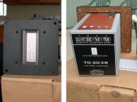
Successful integration of the tweeter ribbon with the midrange will set limits in height, lowest frequency of operation, and maximum SPL. The center-to-center distance will determine the required crossover frequency to minimize lobing. The idea is to keep C-to-C below 1/4 of the crossover frequency wavelength, but 1/2 wavelength is often accepted as the longest compromise. The ribbon's highest frequency will set the optimal ribbon width. The required SPL will set ribbon area = height * width. RAAL's new 70x20 short-and-wide ribbon is starting to become popular because it gives up some of the highest frequency extension to keep a modest physical height to control T-M lobing.
MINIMUM REAR CAVITY EFFECTS: To minimize rear cavity reflections to the back of the ribbon, as well as minimize cavity resonances, some monopole ribbons are constructed with just N+S pole steel as might be done for a dipole ribbon. Extensive dampening material is still used behind the ribbon, but with fewer volume restrictions. Some pole cavity partitioning can help raise resonance frequencies. A few thin rear steel cross braces can increase the gap flux with a modest sonic signature.
Successful integration of the tweeter ribbon with the midrange will set limits in height, lowest frequency of operation, and maximum SPL. The center-to-center distance will determine the required crossover frequency to minimize lobing. The idea is to keep C-to-C below 1/4 of the crossover frequency wavelength, but 1/2 wavelength is often accepted as the longest compromise. The ribbon's highest frequency will set the optimal ribbon width. The required SPL will set ribbon area = height * width. RAAL's new 70x20 short-and-wide ribbon is starting to become popular because it gives up some of the highest frequency extension to keep a modest physical height to control T-M lobing.
Attachments
Here is a company that sells small quantity orders of aluminum, steel and other types of metals of all shapes and sizes that you could and should take advantage of..
Online Metal Store | Small Quantity Metal Orders | Metal Cutting, Sales & Shipping | Buy Steel, Aluminum, Copper, Brass, Stainless | Metal Product Guides at OnlineMetals.com
Online Metal Store | Small Quantity Metal Orders | Metal Cutting, Sales & Shipping | Buy Steel, Aluminum, Copper, Brass, Stainless | Metal Product Guides at OnlineMetals.com
Last edited:
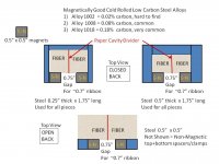
I sketched a few tweeter ribbon top view construction ideas for brain trust discussions. I use the open back design with 0.5" x 0.5" N50 NdFeB magnets on 0.5" x 0.5" steel pole pieces since I can use it as either a monopole with rear stuffing or as a dipole without stuffing. Lately I've been using 0.7" and 1" wide 5.4um and 8um embossed aluminum foil ribbons to push down the safe LR4 crossover frequency close to 1.1Khz at the expense of some high frequency beaming because I favor using a 7"-10" midbass to cover 100-1200Hz.
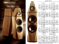
MY FAVORITE PHOTOSHOP RIBBON SPEAKER: If you ever sketch up a few 3-way cabinets using your ribbon tweeter a shape like the Avalon Isis might be worth consideration. Olson's early research into cabinet diffraction motivated speaker companies like Avalon to evolve a version of the truncated pyramid on parallelopiped baffle shape. Reduces diffraction, looks sexy(abstract Chess Bishop), easier to build than a sphere. The Isis uses a very expensive 7" midrange, but there are modest cost 7"-8" midranges with 94-96 db/watt efficiency that can approach the ribbon efficiency without beaming at ~1.2KHz - 1.4Khz LR4 Xover.
MY FAVORITE PHOTOSHOP RIBBON SPEAKER: If you ever sketch up a few 3-way cabinets using your ribbon tweeter a shape like the Avalon Isis might be worth consideration. Olson's early research into cabinet diffraction motivated speaker companies like Avalon to evolve a version of the truncated pyramid on parallelopiped baffle shape. Reduces diffraction, looks sexy(abstract Chess Bishop), easier to build than a sphere. The Isis uses a very expensive 7" midrange, but there are modest cost 7"-8" midranges with 94-96 db/watt efficiency that can approach the ribbon efficiency without beaming at ~1.2KHz - 1.4Khz LR4 Xover.
Attachments
Last edited:
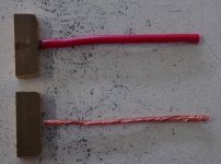
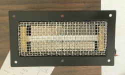
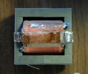
Ribbon Tweeters FINALLY Finished
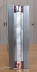
I finally finished the 4 inch ribbon tweeters. I figure 4 of them is enough! They were a lot of work to make look good. They are over twice as loud as any tweeter I have bought and a lot clearer.
Ray
____________________________________________
If brute force doesn't work, your not using enough of it!
Attachments
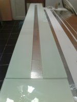
Low Impedance to 8 Ohm
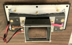
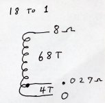
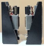
Yes, .027 ohm. Transformer on back is 18 to 1. It is basically primary inside of a copper tube. Idea is used for wideband high power RF amplifiers and works very well for this also. I have many photo's of one being made. Not an easy project.
Yes, .027 ohm. Transformer on back is 18 to 1. It is basically primary inside of a copper tube. Idea is used for wideband high power RF amplifiers and works very well for this also. I have many photo's of one being made. Not an easy project.
Attachments
ooh wow, they are not even expensive. so i just do for instance wire of 8 times 18 turns paralel, and put them in a one turn coper foil (tube) to make a 1:18 ratio trannie ?
so approx 10 dollars for the core and some magnet wire and foil ?
hmm looks cool. i got a winding machine so might finally put the old beast to use again")
although with this low nr of turns it hardly is any benefit
so approx 10 dollars for the core and some magnet wire and foil ?
hmm looks cool. i got a winding machine so might finally put the old beast to use again
although with this low nr of turns it hardly is any benefit
Last edited:
Yes, .027 ohm. Transformer on back is 18 to 1. It is basically primary inside of a copper tube. Idea is used for wideband high power RF amplifiers and works very well for this also. I have many photo's of one being made. Not an easy project.
im in a project i used resistors for my ribbon but they didnt lasted long i was searching for this kind of a transformer to build one to my ribbon tweeter mine is a big one and its 1.4 Ohm-s in room temperature measured, i dont know where to start for the transformer
Attachments
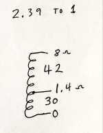
It is made of 4 of the tube things in series. 17 turns in each, so when done total of 72 turns and a tap. You can see the 4 soldered tube layers in photo.
For 1.4 ohm ribbon, it is 2.39 to 1 so 72 turns with tap at 30 turns if lowest frequency is 3 KC. This is using the EDT cores I listed, and 2 #21 wires in parallel. If lower frequency is wanted, need more total turns. 144 will give you 1.5 KC, but would have to use only one # 21 wire to fit the core, and that will make resistance of total winding around 1 ohm, but the loss would be a lot less than a resistor. Probably better to use interleaved winding with amorphous core for lower frequency.
For 1.4 ohm ribbon, it is 2.39 to 1 so 72 turns with tap at 30 turns if lowest frequency is 3 KC. This is using the EDT cores I listed, and 2 #21 wires in parallel. If lower frequency is wanted, need more total turns. 144 will give you 1.5 KC, but would have to use only one # 21 wire to fit the core, and that will make resistance of total winding around 1 ohm, but the loss would be a lot less than a resistor. Probably better to use interleaved winding with amorphous core for lower frequency.
Attachments
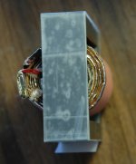
It is made of 4 of the tube things in series. 17 turns in each, so when done total of 72 turns and a tap. You can see the 4 soldered tube layers in photo.
For 1.4 ohm ribbon, it is 2.39 to 1 so 72 turns with tap at 30 turns if lowest frequency is 3 KC. This is using the EDT cores I listed, and 2 #21 wires in parallel. If lower frequency is wanted, need more total turns. 144 will give you 1.5 KC, but would have to use only one # 21 wire to fit the core, and that will make resistance of total winding around 1 ohm, but the loss would be a lot less than a resistor. Probably better to use interleaved winding with amorphous core for lower frequency.
Thank you for your help i will test it
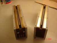
These things are finally playing music! I decided to finish the first 2 as stand alone, not put in a speaker box. They are with Acoustic Research Series 660 speakers I got from a friend many years ago. They are in perfect shape, but adding these tweeters added highs that were never there before. Also found that blowing into them to remove dust destroys the ribbon!
Attachments
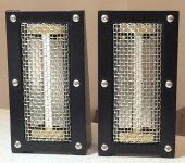
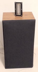
These things are finally playing music! I decided to finish the first 2 as stand alone, not put in a speaker box. They are with Acoustic Research Series 660 speakers I got from a friend many years ago. They are in perfect shape, but adding these tweeters added highs that were never there before. Also found that blowing into them to remove dust destroys the ribbon!
At what frequency do you cross over ? Do we get to see a FR? What a fantastic ribbon
Inspirational!Crossover at 4000 Hz 3rd order. I have no way to test for the actual response of them, but they been playing for 5 months and I really enjoy the sound. Compared to other tweeters, they are a lot louder, cleaner, and actually play the very high notes clearly which were missing before.
These things are finally playing music! I decided to finish the first 2 as stand alone, not put in a speaker box. They are with Acoustic Research Series 660 speakers I got from a friend many years ago. They are in perfect shape, but adding these tweeters added highs that were never there before. Also found that blowing into them to remove dust destroys the ribbon!
These look fantastic, well done. Is there a step-by-step guide, especially for the big material work like drilling and setting up, etc?
- Status
- This old topic is closed. If you want to reopen this topic, contact a moderator using the "Report Post" button.
- Home
- Loudspeakers
- Planars & Exotics
- DIY 4 Inch Ribbon Tweeter