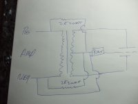
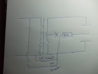
Looking at the schematics of most manufacturer's ESLs, you will see that the secondary side of the step-up transformer is referenced to safety ground (figure A in attachment) or the primary of the step-up transformer (figure B in attachment).
But, most DIY ESLs are built with the secondary side of the transformer floating free (figure C in attachment).
So, does anybody have a good explanation why most manufactured ESLs have the secondary referenced to safety ground or the primary? It had been suggested to me that perhaps with the secondary side floating, it could build up considerable static potential relative to the primary and the rest of your electronics. Most likely, it is to cover some sort of safety concern like this, I'm just not certain of what. Thoughts?
Attachments
Personaly I would much prefer the total Isolation of C.
I am currently using the configuration in A and I think that it is much safer.
And also because of the way my power supply is configured so that I can have measurements of the high voltage that it produces.
This also keeps the step up transformer secondary's at ground potential reducing the potential of Bias voltage punching through the transformers winding's.
The configuration in B could cause some issues with the amplifier should the user reverse the polarity of the feed line coming from the amplifier.
I just solved ( but not completely) an issue last night where I had to use a 1ohm resistor in series with the primary winding in order for my DC300A to not freak out as it sits idle with no input signal.
As it turned out the scopes ground was connected to the ground side ( or maybe it is not but what I thought was) of the amp causing some issue and would spark and freak out if I connected the winding without the 1 ohm resistor.
The amp still was not performing correctly any how for some reason.
The resistor finally burned out and then I disconnected the ground lead from the scope but left the input lead to the scope and all is well now ,the amp works perfectly with no issues and I am reading waveforms on the scope with just the input lead connected.
There maybe some kind of ground fault issue and I will have to look into this and maybe the reason that I have some residual 60hz floating on my otherwise quiet 120db below 0db noise floor.
jer")
I am currently using the configuration in A and I think that it is much safer.
And also because of the way my power supply is configured so that I can have measurements of the high voltage that it produces.
This also keeps the step up transformer secondary's at ground potential reducing the potential of Bias voltage punching through the transformers winding's.
The configuration in B could cause some issues with the amplifier should the user reverse the polarity of the feed line coming from the amplifier.
I just solved ( but not completely) an issue last night where I had to use a 1ohm resistor in series with the primary winding in order for my DC300A to not freak out as it sits idle with no input signal.
As it turned out the scopes ground was connected to the ground side ( or maybe it is not but what I thought was) of the amp causing some issue and would spark and freak out if I connected the winding without the 1 ohm resistor.
The amp still was not performing correctly any how for some reason.
The resistor finally burned out and then I disconnected the ground lead from the scope but left the input lead to the scope and all is well now ,the amp works perfectly with no issues and I am reading waveforms on the scope with just the input lead connected.
There maybe some kind of ground fault issue and I will have to look into this and maybe the reason that I have some residual 60hz floating on my otherwise quiet 120db below 0db noise floor.
jer
Last edited:
There needs to be NEW look at this but i gess most just see it like the bias....if it works an it NOT in the audio path .... I think it all is?
I have found just having a better bias tranfourmer with more VAmps or a diff V...like 1000 v then setping up to say 5k... Can sound better than 250v tranfourmer!
The THD can be so low on ESL next to any other panel or piston type...thay just take a pass
Thanks for this post
I have found just having a better bias tranfourmer with more VAmps or a diff V...like 1000 v then setping up to say 5k... Can sound better than 250v tranfourmer!
The THD can be so low on ESL next to any other panel or piston type...thay just take a pass
Thanks for this post
Bolserst
I just got a pr of ML Ascent i....An thay sound to good so i had to look..at the setup.There set up on the centertap
No earth In this setup!
An looking at the bias board here we have a nother for your pic of the gronding....
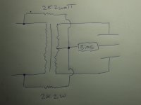
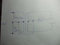
ML here is set up like C in the pic on the right....but thay have taken the crossover[ Neg. An Pos.] right off the binding post...An feed them to the 0 bias an centap point though 2kohm 2watt res. ...The other pr of ML Ascents
I have beed puting the bias 0 point back in like D.....But With D now i am comeing in with the Neg an the Pos. feed in though the 2k res.....sound great ...
Can you give some info on this or your thinking...Have you seen this one.
Thank for your time
I just got a pr of ML Ascent i....An thay sound to good so i had to look..at the setup.There set up on the centertap
No earth In this setup!
An looking at the bias board here we have a nother for your pic of the gronding....
ML here is set up like C in the pic on the right....but thay have taken the crossover[ Neg. An Pos.] right off the binding post...An feed them to the 0 bias an centap point though 2kohm 2watt res. ...The other pr of ML Ascents
I have beed puting the bias 0 point back in like D.....But With D now i am comeing in with the Neg an the Pos. feed in though the 2k res.....sound great ...
Can you give some info on this or your thinking...Have you seen this one.
Thank for your time
Attachments
![HV_configs[1].gif](/community/data/attachments/246/246876-e6bd20f0803fa6b2a913a518508e4fd9.jpg)
![HV_gnd_ref[1].gif](/community/data/attachments/246/246883-0c5a06da42c17344aea4811d146b0f05.jpg)
The CLX has a 3 pole AC connector so you can connect fancy AC line cords for them. Martin Logan do not use the AC ground pole at all to connect to anything internally, the AC ground is just left floating. I didn't trace the HF and LF transformer secondaries back to see what primary reference there may be.
Here is some bad Art but you can see there setup here...This sound good
An yes the earth is out on most newer ML ESL that i have seen...the Sequal an the frist CLS had earth....Any info on the CLX tranfourmer setup well help a lot..
thanks for any info on ESL
An yes the earth is out on most newer ML ESL that i have seen...the Sequal an the frist CLS had earth....Any info on the CLX tranfourmer setup well help a lot..
thanks for any info on ESL
Attachments

Bolserst
I just got a pr of ML Ascent i....An thay sound to good so i had to look..at the setup.
An looking at the bias board here we have a nother for your pic of the gronding....
ML here is set up like C in the pic on the right....but thay have taken the crossover[ Neg. An Pos.] right off the binding post...An feed them to the 0 bias an centap point though 2kohm 2watt res.
...
Can you give some info on this or your thinking...Have you seen this one.
Hello Tyu,
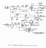
I have seen this setup before. It is the same as the standard SL3 connection.
Looking at attached SL3 schematic, I put large arrows pointing to the 2K resistors in the auto turn on sensing portion of the schematic.
For those stumbling on this topic later, I also attached a *.pdf of the standard SL3 crossover and wiring diagram that tyu had posted elsewhere.
It may interest you that the ML Spires use a similar but slightly different arrangement where the center tap of the primary is used for reference rather than the midpoint of two 2K resistors.
I added these two arrangements as D & E in the schematics summary figure.
As far as why ML feels it is important to provide some connection, or reference, between the secondary and the primary, I don't know. We all know arrangement C works just fine with no reference to safety ground or the primary. That was why I started this thread, to see if anybody knew why manufacturers like ML and QUAD felt it important to include this connection.
Attachments
Great...thanks for the pic... it looks like ML has done a lot of diff setups on ESL....to bad the dont bild the panels the way thay could to get more output an last for a longer time by runing the bias feed diff.....i well say it hard to live with any stock ML panels after you heard a panel with two bias feeds......
In the SL3.... ones with the limiter an one with out..thay allways had a wire ran from the crossover neg to the same point as the bias 0 an the center tap...so this jumped the neg res.....but the pos.res was still in the mix.....this is what i did at frist with my reg. Ascents
So SL3 were diff than the Ascent you can see on the pic you posted....an the Ascent i only has the D setup
An i well say it sound diff...with just D... thats the neg an the pos.only as a ref..an sounds the best so far.
So SL3 were diff than the Ascent you can see on the pic you posted....an the Ascent i only has the D setup
An i well say it sound diff...with just D... thats the neg an the pos.only as a ref..an sounds the best so far.
ForGive the art....post this SL3 setup so other can see how to do a mod if thay would like ..The pic on the left is the SL3...An can be seen on the schematic...the extra neg wire that should not be there...Runs to the bias board...an is not there on all the newer setups..
bolserst
Now on the ML Spires ....on the right... is this right...the 2k are on the bias board with the limiter..Do you have any more info on the Spires..
An how about the CLX i like to see the xover...an tranfourmer setup an bias board..An limiter?
Thanks
bolserst
Now on the ML Spires ....on the right... is this right...the 2k are on the bias board with the limiter..Do you have any more info on the Spires..
An how about the CLX i like to see the xover...an tranfourmer setup an bias board..An limiter?
Thanks
Attachments
bolserst
Now on the ML Spires ....on the right... is this right...the 2k are on the bias board with the limiter.
The bias/limiter board for the Spires does not use the 2K resistors from the audio input like the SL3. It is just as shown in arrangement "E" from post#9.
Dayton Wright used 2k2 from each polarity of input jack to chassis ground to establish ground reference.
Do you know which DW ESLs used the 2k2 resistors?
The only DW schematic I have is for the XG-10 which shows HV bias connected to center tap and referenced to safety ground. (ie Arrangement "A" from post#9)
Attachments
I have Dayton Wright ST 300, and IM 10 interfaces - both have 2k2 resistors from each input connector to ground, yes they are not shown on the schematic. Have Dayton Wright XG 8 mk 3 , XG 10, XG 10 mk ii. I also have have Dayton Wright IM 11 interface, but not opened it yet. Also have Quad 63, Acoustat model 1, ML Request and CLX - too many electrostatics too little time. Double pair of Dayton Wrights is very good especially in the bottom end - my other favorites are modified CLX's with ribbon top end and subs.
I have Dayton Wright ST 300, and IM 10 interfaces - both have 2k2 resistors from each input connector to ground, yes they are not shown on the schematic. Have Dayton Wright XG 8 mk 3 , XG 10, XG 10 mk ii.
Thanks for the DW info.

Did the ST 300 and IM 10 interfaces connect the AC safety ground like the XG-10 schematic?
Or, is the AC safety ground left hanging free like your CLX.
The IM 10 was interface for XG 10 speaker. The St 300 was for XG 8 speaker.
The interfaces are pretty similiar, they differ only in teeeter crossover - piezo ceramic in XG 8 and Panasonic leaf teeeter in XG 10. There is also an small inductor in series with the electrostatics. The inductor value changed a little in the two interfaces and the cells could be run fill range in the IM 10 if you had the right amplifier which could drive them. I'm just hearing from some - one who hot roded the DW interfaces (like Nelson Pass / Joe Sammut Threshold did) and drives the DW cells directly with just a .22r buildout resistor in a double pair arrangement. The user adjustable bias voltage range may have been lowered to 11kv from the 17? Kv max if I recall correctly when they changed models.
The speakers were rebuilt over the years as SF 6 leaks or bad cells occoured snd old and new cells were used with old and new interfaces so there are versions of both interfaces with both versions of cells.
The safety AC ground was always connected to chassis on all models of interface.
Last edited:
bolserst
Thanks for all your time an help for myself an others.....
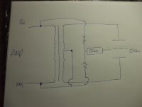
I have been reworking an play with the setups you an others have siad Is the way that ESL work.. What i have found with the com.Centap setup for ESLs.
What i called a Fluk that ML made with the bias floting is not the case.
we know now the there were a 2k 2watt.feed to the bias 0 from the pos.an the neg on the Amp Primary side so with the centap just ran to the neg input an not the 0 was how it worket.... are you saying the panel wont charg all the way up?
As i have siad it sound much better this way.In the testing i have done with other thay all say this sounds the best.Art on the left
I have fond that if the bias 0 is put on the center tap there is a noise i call it AC in the highend of the sound .
Now i no this is one man thinking an it can mean a lot to ME..but to others it may mean nothing.
Now as for the SE setup i use,The art on the right, all i have here is a Ratshak soundpresurmeter
but i get almost 2db more output from 1'away with this setup .
Forgive the art
I have put the Art in here so other can see...thanks for any input on ESLs
Thanks for all your time an help for myself an others.....
I have been reworking an play with the setups you an others have siad Is the way that ESL work.. What i have found with the com.Centap setup for ESLs.
What i called a Fluk that ML made with the bias floting is not the case.
we know now the there were a 2k 2watt.feed to the bias 0 from the pos.an the neg on the Amp Primary side so with the centap just ran to the neg input an not the 0 was how it worket.... are you saying the panel wont charg all the way up?
As i have siad it sound much better this way.In the testing i have done with other thay all say this sounds the best.Art on the left
I have fond that if the bias 0 is put on the center tap there is a noise i call it AC in the highend of the sound .
Now i no this is one man thinking an it can mean a lot to ME..but to others it may mean nothing.
Now as for the SE setup i use,The art on the right, all i have here is a Ratshak soundpresurmeter
but i get almost 2db more output from 1'away with this setup .
Forgive the art
I have put the Art in here so other can see...thanks for any input on ESLs
Attachments
- Status
- This old topic is closed. If you want to reopen this topic, contact a moderator using the "Report Post" button.
- Home
- Loudspeakers
- Planars & Exotics
- Ground reference for ESLs