The 2K resistance is small compared to the 10Mohm or more resistance between the bias supply and the diaphragm. These two resistance are in series when charging the panel, so the 2K resistance has little affect on how much the panel can charge up.bolserst
are you saying the panel wont charg all the way up?
I tested one more time last night and do not get any change in SPL between the two setups.Now as for the SE setup i use,The art on the right, all i have here is a Ratshak soundpresurmeter but i get almost 2db more output from 1'away with this setup .
The output of an ESL panel is dependent on two things, 1) diaphragm charge and 2) stator voltage.
To get 2dB more output, one of those two things had to increase by 30%, assuming the microphone placement and test signal were the same.
Was there any other changes you made? I know you had posted elsewhere about a bias modification that increased the bias voltage.
bolserst
I saw the Acoustat 11 you posted...thay used the 10m too the bias 0 That would let it flot up right....there nothing new ...it al l been done ...we just have to find the info
ML Spres do you have the schematic ? anyone CLX
I dont no about the more output...i trust you... i have seen your work here, Thanks for all of it
Yes what i have been doing is geting a good 10m res. an puting it in on the Logan a bias feed...thay have 5 15m1/4watt carbon...not bad sounding..but this dose give more bias..
but as for more out put...you can hear a change right off ...
The testing was done with the bias 0 in the setup ...no res. but this sounds hard..i put more res. 60m back in the bias feed that helpet...but when i went back two the 2k feed souned much better...this sound i am talking about sounded like you were driveing the 2k hard with a amp...but sweetins up with the 2k feed.Still working on it all
Thanks
bolserst
Bingo...it was the 2k res...pulled them an now were back to your frist post I have C in now and.....
Does anybody have a good explanation why most manufactured ESLs have the secondary referenced to safety ground or the primary? It had been suggested to me that perhaps with the secondary side floating, it could build up considerable static potential relative to the primary and the rest of your electronics. Most likely, it is to cover some sort of safety concern like this, I'm just not certain of what. Thoughts?
Good sound ..mAX the output. OUT OF THE PANEL..i can dig this ... boy all those SL3 out there sounding hard ...it the 2k res. JUST LIFT THEM..
Now i have put the SL3 power supply up i no you have this but i would like you to look at this an tell me how i can bypass the turn on an juSt say on all the time ... it looks To me like the switch is just the bias 0...When the 0 in it truns on... can you give me some input....thanks
Attachments
how i can bypass the turn on an juSt say on all the time ... it looks To me like the switch is just the bias 0...When the 0 in it truns on... can you give me some input....thanks
There are many ways to force the SL3 bias supply to stay ON. Here are two.
1) Solder a wire as shown to bypass the TRIAC switch. The bias supply will stay on. The LED will still turn on with applied audio, and turn after 15 minutes or so after audio is removed.
2) Solder a wire as shown to short out C6. The bias supply and LED will stay on whether or not there is audio applied.
Attachments
Secondary Ground Reference
So, does anybody have a good explanation why most manufactured ESLs have the secondary referenced to safety ground or the primary? It had been suggested to me that perhaps with the secondary side floating, it could build up considerable static potential relative to the primary and the rest of your electronics. Most likely, it is to cover some sort of safety concern like this, I'm just not certain of what. Thoughts?[/QUOTE]
Perhaps there is concern over long-term reliability of the step-up transformer insulation with the HV bias leakage across the primary/secondary boundary. In theory there should be no leakage but floating charge can do strange things. Grounding the CT to the primary with a hard ground or through a resistance would prevent this.
I agree with Mike. We like to think in circuit diagrams but with high voltages like this leakage paths develop very easily. I once forgot to put the 'ground' wire between the high voltage supply and the step-up transformer, so the HT was left floating. The speaker was working just fine, it completed the loop with the wooden frame (about 30cm distance between HT and step-up).
Quad grounds the CT secondary and the core as well. The primary is left floating.
Quad grounds the CT secondary and the core as well. The primary is left floating.
Perhaps there is concern over long-term reliability of the step-up transformer insulation with the HV bias leakage across the primary/secondary boundary. In theory there should be no leakage but floating charge can do strange things. Grounding the CT to the primary with a hard ground or through a resistance would prevent this.
Hey Mike,
Thanks for bringing this thread back on topic.
Hmmmmm...perhaps one could setup a buffered(ie extremely high input impedance) HV probe to measure the voltage across the primary/secondary boundary with the secondary floating to determine if this is the case.
Hello arend-jan,I once forgot to put the 'ground' wire between the high voltage supply and the step-up transformer, so the HT was left floating. The speaker was working just fine, it completed the loop with the wooden frame
I have had similar experiences where unconnected bias supply wires were actually charging up the diaphragm thru the resistance of the MDF base they were laying on. The HV bias supply doesn't need a low resistance connection to the transformer/Stators. The series resistance just defines the time constant for charging up the panel. Well, I guess in practice a portion of the bias supply voltage is dropped across the series resistance; the magnitude of the drop being propotional to the leakage current.
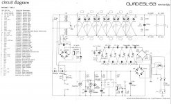
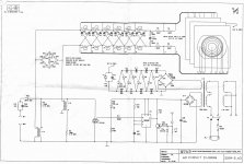
Yes, the original Quad ESL and the early versions of the ESL63 connected the secondary CT to safety ground.Quad grounds the CT secondary and the core as well. The primary is left floating.
I have always wondered why in later versions of the ESL63 the connection to safety ground was removed, and the secondary CT was connected to the primary.
Attached are early/later schematics of the ESL63 to illustrate this change.
Attachments
I don't know the answer to that. But I'm willing to take a guess.
In the older models the high voltage section (stators, EHT) is referenced to safety earth and the whole input section, including spark detector, seems to be left floating (or actually referenced to whatever the amplifier is doing). Perhaps there were problems with the reliability of the spark detector? It seems preferable to have the spark detector referenced to the high voltage section in a predictable manner, not just by parasitics and whatever amplifier is hooked up.
In the later models the input section and the high voltage section are referenced to the same internal ground. Which means connecting it so safety earth would connect one of the speaker input terminals to safety earth. Not all amplifiers are going to handle that gracefully so that might be the reason to keep the whole speaker floating?
I don't know the answer to that. But I'm willing to take a guess.
Perhaps there were problems with the reliability of the spark detector? It seems preferable to have the spark detector referenced to the high voltage section in a predictable manner, not just by parasitics and whatever amplifier is hooked up.
Interesting thought...certainly the spark detector would be more sensitive to the RF energy emitted during arcing if the detector was referenced to part to the circuit through which the spark would conduct. However, several other ESL companies use the later arrangement where the primary and secondary are tied together and do not have a spark detector circuit to concern themselves with. Perhaps they just followed Quad's lead without much thought put into it? Wouldn't be the first time circuit arrangments were borrowed and used without fully understanding them.
In the later models the input section and the high voltage section are referenced to the same internal ground. Which means connecting it so safety earth would connect one of the speaker input terminals to safety earth. Not all amplifiers are going to handle that gracefully so that might be the reason to keep the whole speaker floating?
Interesting that you should mention this since I just recently read on the ML forum that some models(the Quest was mentioned) had this arrangement and would destroy the output stages of balanced power amplifiers that were connected to safety ground through their own power cord.
Bolserst
Thanks for the Quad info...looks like thay were using the {limiter} way back whin...What is that a NPN..PNP..no fet??...an how about that Cap..1.5uf
nothing is new....
Power BJT technology was much more mature back in the 60s than power FET. I'm sure that weighed in to the decision to use a BJT device for the limiter rather than a MOSFET. Most likely the 1.5uF cap is there to filter out the voltage transients from when the NPN transistor attempts to turns OFF after limiting a voltage peak.
Yes it does seem sometimes that we keep re-discovering old ideas.
This seems to be the case when technological advances are considered proprietary and are not patented or published.
My Icepower amp, for instance, does not have the amp speaker ground referenced to ground, so forcing it to ground could destroy the amp. I have my ESL floating...
Wouldn't this also apply to any amp that is bridged?
Absolutely.
Connecting safety ground to the (-) speaker input terminal on an ESL is just not a good idea.
You guys are fkn awesome , Newbie here but my outside observations are these.
After reading these post and looking at how ML used to do things I would like to add that older panels sounded worst than newer versions by default IE Electromotions => Vistas. Not sure if it has to do with with their power setups or Crossovers but Since we have a Spire diagram it would be nice if we could compare that to the Summit or Montis setup . The last ESL they made would have used their latest techniques when it came to safety right? but also modifications so that it wouldn't sound as good , I happen to have a pair that I could take pics of the internals and send them to you guys if it would help in any way .
After reading these post and looking at how ML used to do things I would like to add that older panels sounded worst than newer versions by default IE Electromotions => Vistas. Not sure if it has to do with with their power setups or Crossovers but Since we have a Spire diagram it would be nice if we could compare that to the Summit or Montis setup . The last ESL they made would have used their latest techniques when it came to safety right? but also modifications so that it wouldn't sound as good , I happen to have a pair that I could take pics of the internals and send them to you guys if it would help in any way .
To address the original question about the mysterious variations, Mike Wright used to complain bitterly about what he felt were the nonsense requirements set for him by the Canadian Standards Assn (analogous to "UL Approved"). So maybe the configurations depend on the bodies doing the regulating and their incomplete grasp of the safety situation for ESL gear submitted to them.
Ben
Ben
Dynamik...........yes send me all the info on any an all on the Logans stup....i get logans all the time...more the better..........thanks for your time
This sounds nuts but this ESL setup is ongoing for me..........To day with the older Logans i put the saty ground on the bias....then run though a 500 ohm res to the centap of the stepup tran....
On full rang ESL like Acoustas i run the saty ground to the center taps of the setup trans an then run a 500ohm to the bias...........an pull the metel case out of the saty ground...an let it flot.....Sound is way better....to me!
Last edited:
I cant see how runing any amps outputs pos-neg into two 2k an then togather ....can sound better.....but logan dose this also... in there on an off bias setup ....
Best sound i get out of the ML is to set the bias up were the panels are fed bias all the time.....after two days you can hear a diff....an by doing this you can get the 2k res on the pos-neg amp feeds out ...
The saft-ground has no place in the logan bias....after puting it back in....it dose sound better out!...on the older ML bias setups thay do put a res like 50ohms in be tween the cetap...
I think May be the SL an the Acoustats useing two diff transfourmer types in there interface setups ........the saft ground can be in the mix....an sound good?
But in the end floting the bias off the saft ground....has to sound better less the two diff trans ran togather thought the Mixer... work better with the one saft ground?
- Status
- This old topic is closed. If you want to reopen this topic, contact a moderator using the "Report Post" button.
- Home
- Loudspeakers
- Planars & Exotics
- Ground reference for ESLs