Henry, of course weight matters.
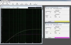
See a simulation of two identical drivers (ScanSpeak 6,5 inch) in a 10000 l box (approx. infinite baffle).
One has a moving mass of 17,5 gram, the other doubble up. Input is 10W. Difference is 6 db.
I'm not sure I understand what you mean by epsilon layout. Please explain or point to a place where it is explained. Thanks in advance.
Kind regards Baldin")
See a simulation of two identical drivers (ScanSpeak 6,5 inch) in a 10000 l box (approx. infinite baffle).
One has a moving mass of 17,5 gram, the other doubble up. Input is 10W. Difference is 6 db.
I'm not sure I understand what you mean by epsilon layout. Please explain or point to a place where it is explained. Thanks in advance.
Kind regards Baldin
Attachments
This webiste may be of interest: Planar Loudspeakers Ribbon Foil Speakers Project, magnetostatic design
Hi Nelson Bass (funny user name )
La Flolia, that is just the "normal" way .... you run one or more wires/conductors between alternating polarized magnets .... looking at the epsilon speakers, that's exactly the same way. So what is it Henry is refering to. To my mind his magnets are set way to close together (no way for the air to pass = compression)... is this what he is refering to? Or that you run more wires between the magnets (which will of course raise the BxL factor) ..... Best regards Baldin
)La Flolia, that is just the "normal" way .... you run one or more wires/conductors between alternating polarized magnets .... looking at the epsilon speakers, that's exactly the same way. So what is it Henry is refering to. To my mind his magnets are set way to close together (no way for the air to pass = compression)... is this what he is refering to? Or that you run more wires between the magnets (which will of course raise the BxL factor) ..... Best regards Baldin
Henry, of course weight matters.
See a simulation of two identical drivers (ScanSpeak 6,5 inch) in a 10000 l box (approx. infinite baffle).
One has a moving mass of 17,5 gram, the other doubble up. Input is 10W. Difference is 6 db.
I'm not sure I understand what you mean by epsilon layout. Please explain or point to a place where it is explained. Thanks in advance.
Kind regards Baldin
Post #98 at http://www.diyaudio.com/forums/planars-exotics/200038-analysis-epsilon-10.html .
Hi Baldin
thank you very much for the advise, think I will try without corrugation, higher tension, foam surround for damping and a cloth at the rear face to control the response.
I'm also thinking on increasing a bit the surface in order to go a little lower.
The point is that the mini maggies and the eminent LFT 11 go to around 200 Hz
so "If its happen, it must be possible" isn't it?
Wish me luck!
and thank you again for the input
BTW nice blog, I've enjoyed it a lot
A4 mini planar
Hi Henry
If you are thinking on rebuilding A4 planars with Epsilon layout, please hurry up!
I just can't wait to know how it goes.
A4 is the max size I can afford to desktop planars.
Still, it's rather difficult use epsilon with the magnets on hand (2mm!)
Kind regards, and don't stop rewiring...
Pedro
Won't be building the new version yet, still too busy building bigger rebuilds, which are more important to me. What with the cost of all the magnets. I have built many rebuilds and as I experiment with different layouts etc, you live and learn, as I am more interested in the mechanical side of things, I leave all the electronic variations to the experts. I will be building a headphone device using the same principals which will be of some interest to you,vis a vis cost.
I'm not sure I understand what you mean by epsilon layout. Please explain or point to a place where it is explained. Thanks in advance.
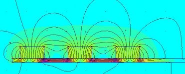
I'm still trying to nail down the defining characteristic of "the Epsilon layout" as well. I don't think the details of the serpentine conductor pattern, meaning the way the conductor loops around after completing a run in one direction and prepares for a run in the opposite direction, are the key point. The increased sensitivity seems most likely to come from increasing the length of wire immersed in the magnetic field: the BL product (magnetic field strength times length of conductor) is larger. More conductor means more mass but also more force.
I remain a bit baffled by the usefulness of running a conductor in a region of space where the magnetic field lines run largely perpendicular to the diaphragm rather than parallel to it. Since the pictures of the magnet arrays don't include labels of N and S poles maybe I'm making some bad assumptions about the layout.
A cloth made the business
Thank you again for the help
I've skip the corrugation, stretched the diaphragm as tight as posible, eliminate the wrinkles, and the panel now sounds a lot less distorted.
The final touch, was put a cloth at the back, improving the bass response a lot. The movement of the membrane is reduced and more controlled.
I'm very satisfied.
Now I can start another prototype with asimetric membrane (Apogee style)
And a little more surface. If it works then will be ready to make a pair with a finish less "utilitarian"
It's very clear that it must have a subwoofer, but that's another history; planar or cones? Mmmmm
Hi Karrellen
Looks like you have gotten the same idea as I about use of perforated steel plates with square holes
Couple of things:
1. Be careful of the weight of the diaphragm, as it will limit upper frequency and sensitivity. Therefor use very thin plastic ... less than 12 micrometers. Same goes for the alu foil ...
2. Skip the corrugation, and use something at the edges as dampeners (foam, rubber ...)
3. Be very careful when stretching the diaphragm (looks like you have wrinkles, and these will for sure make distortion). It also have to be quite tight not to hit the back panel a low freq.
4. A small planer like this will not play any bass ... think you need to consider a dynamic woofer for the bass .... .... this size I think is not good for under 500 Hz at best ..... unless you are playing at very low levels
Keep it up, you are on the right track for sure ...
Best regards Baldin

Thank you again for the help
I've skip the corrugation, stretched the diaphragm as tight as posible, eliminate the wrinkles, and the panel now sounds a lot less distorted.
The final touch, was put a cloth at the back, improving the bass response a lot. The movement of the membrane is reduced and more controlled.
I'm very satisfied.
Now I can start another prototype with asimetric membrane (Apogee style)
And a little more surface. If it works then will be ready to make a pair with a finish less "utilitarian"
It's very clear that it must have a subwoofer, but that's another history; planar or cones? Mmmmm
I'm still trying to nail down the defining characteristic of "the Epsilon layout" as well. I don't think the details of the serpentine conductor pattern, meaning the way the conductor loops around after completing a run in one direction and prepares for a run in the opposite direction, are the key point. The increased sensitivity seems most likely to come from increasing the length of wire immersed in the magnetic field: the BL product (magnetic field strength times length of conductor) is larger. More conductor means more mass but also more force.
I remain a bit baffled by the usefulness of running a conductor in a region of space where the magnetic field lines run largely perpendicular to the diaphragm rather than parallel to it. Since the pictures of the magnet arrays don't include labels of N and S poles maybe I'm making some bad assumptions about the layout.
Exactly. The number of turns within the magnetic gap, means more force, and better sensivity. How you make the serpentine, won't matter as long as the current runs in the right direction.
You are also right that right above the magnet (in the middle of it) the field will be "directed out of the diaphragm" and will therefor not make a force in the right direction to move it back and forth. A conductor running right over the magnet will actually try to mode the diaphragm sideways .... which probably creates distortion. So to my mind it will be better to have an empty region above the magnet to save weight. Making the conductor go a little over the magnets edge will help though.
And as you still not sure what is meant by "the Epsilon layout" ... which gives higher sensivity.
Best regards Baldin
Attachments
Yes the magnets are the usual layout NSNSNS,etc.The diaphragm does not distort whatsoever.Whether you understand the foil layout, the fact is it is a great improvement in sensitivity with no more distortion than the normal layout. Having rebuilt 3 previous normal diaphragms into the new improved ones, I think I can safely say that it works. As long as you get the correct orientation of the foil, which is very important.I'm still trying to nail down the defining characteristic of "the Epsilon layout" as well. I don't think the details of the serpentine conductor pattern, meaning the way the conductor loops around after completing a run in one direction and prepares for a run in the opposite direction, are the key point. The increased sensitivity seems most likely to come from increasing the length of wire immersed in the magnetic field: the BL product (magnetic field strength times length of conductor) is larger. More conductor means more mass but also more force.
I remain a bit baffled by the usefulness of running a conductor in a region of space where the magnetic field lines run largely perpendicular to the diaphragm rather than parallel to it. Since the pictures of the magnet arrays don't include labels of N and S poles maybe I'm making some bad assumptions about the layout.
Last edited:
Yes the magnets are the usual layout NSNSNS,etc.The diaphragm does not distort whatsoever.Whether you understand the foil layout, the fact is it is a great improvement in sensitivity with no more distortion than the normal layout. Having rebuilt 5 previous normal diaphragms into the new improved ones, and am working on my 6th. I think I can safely say that it works. As long as you get the correct orientation of the foil, which is very important.
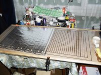
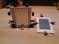
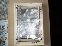
latest rebuild
Used 45 meters of tape only 51/8 finished got to measure how much is required. See if I have enough in my other remains of 45 meters, if not will have to use another 45 meters that is the other half of the cut. The diaphragm will be heavy , all that tape. Will have to use a penny washer to join the 2 layouts.
Used 45 meters of tape only 51/8 finished got to measure how much is required. See if I have enough in my other remains of 45 meters, if not will have to use another 45 meters that is the other half of the cut. The diaphragm will be heavy , all that tape. Will have to use a penny washer to join the 2 layouts.
Attachments
Last edited:
Yes the magnets are the usual layout NSNSNS,etc.The diaphragm does not distort whatsoever.Whether you understand the foil layout, the fact is it is a great improvement in sensitivity with no more distortion than the normal layout. Having rebuilt 3 previous normal diaphragms into the new improved ones, I think I can safely say that it works. As long as you get the correct orientation of the foil, which is very important.
I didn't mean to imply that I don't think it works, I'm just trying to nail down which characteristics contribute to the improvement you're reporting.
Quasi Epsilons
Quasi Epsilon configuration.
I've just finished another mock up of the mini planars. Using the same amount of magnets, *i.e. more or less the same magnetic field, but increasing the util surface, *and puting more Al on the gap.
I called the configuration Quasi Epsilon, but probably it is not. It's just the epsilon with only two conductors per gap or the standard with doble run of Al tape.
The test are encouragin, but still the real test can't be done before a run in time, and a re strech of the membrane.
I'll try to post some pics later
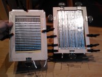
some pics
The quasi Epsilon and her little sister.
the bigger the better.
The sound gets better with the size, the tension of the membrane and the stifness of the frame.
may be one last mock up and ready for a pair on my desktop...
The quasi Epsilon and her little sister.
the bigger the better.
The sound gets better with the size, the tension of the membrane and the stifness of the frame.
may be one last mock up and ready for a pair on my desktop...
Attachments
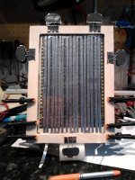
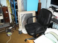
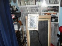
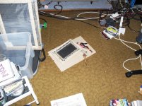
A4 SIZED PLANAR.
I mended the hole with a penny washer always works. Running with the big one on the right at the front on the floor.The A4 is 8.7 ohms. I had to turn the big one down by about 5 Db, so not too bad sensitivity! Not getting hot diaphragm or 25 watt resistor. Not finished yet just a quick mock up to see if it is worth the trouble of building a pair.Quite happy with it so far.
I mended the hole with a penny washer always works. Running with the big one on the right at the front on the floor.The A4 is 8.7 ohms. I had to turn the big one down by about 5 Db, so not too bad sensitivity! Not getting hot diaphragm or 25 watt resistor. Not finished yet just a quick mock up to see if it is worth the trouble of building a pair.Quite happy with it so far.
Attachments


Hi Henry
Impressive handcrafting!
practice made perfection, I suppose.
my target is to achieve 3 Ohms, by reducing the width of the foil.
I think you will be struggling with the sensitivity with your layouts. Although that is what you have with your magnet numbers . I would get more magnets and use the same foil layout as mine. This will significantly increase the sensitivity, which will reduce the heating of the foil etc. I made mine 8.7 ohms to equal my other planars, so I can use these in my 9.1 amplifier set up. If I left it at 4.8 which it is without the 3.9 ohm resistor, I couldn't do this. Why do you want to go that low? Most normal amps are usually 4 or 8 ohms. My new diaphragm is the same weight as the original but is about 3 times more sensitive.
- Status
- This old topic is closed. If you want to reopen this topic, contact a moderator using the "Report Post" button.
- Home
- Loudspeakers
- Planars & Exotics
- Mini planar magnetic using neos