Henry,
I finally looked carefully at the pics in post 98 at http://www.diyaudio.com/forums/planars-exotics/200038-analysis-epsilon-10.html#post2813499 and I think that now I finally see how the Epsilon Layout differs from the old way:
Instead of one run of foil between each column of magnets, there are now basically three, with an extra one on each side of where there was previously just the one in between the magnets. The currents in all three runs are going in the same direction, thanks to the Epsilon Layout, which is the same direction the current would need to go if there was only one conductor between the magnets.
The extra two runs for each gap are actually over the magnets, in your particular layout at that link.
The farther over the magnets a foil run is, the less good it does, since the component of the force that's perpendicular to the mylar gets lower, away from the gap.
In the gap is where the magnetic field is mostly (or at least more) parallel to the mylar and that's what will produce force on the foil that's perpendicular to the mylar. But over the magnets, the field could mostly be going "upward" toward the mylar out of the North poles or downward into the South poles after having gone across the gap. So those fields over the magnets could tend to produce forces with dominant components that are more parallel to the mylar's surface, which would not be doing as much good as they could.
So it seems like you should be putting the three foil runs for each gap as close together as possible, so they are as close to the center of the space between the columns of magnets as possible, with as little foil over the magnets as possible.
Rather than making the foil runs evenly spaced, grouping them (toward the gaps) that way would tend to leave an unused space over the center of each column of magnets. That should improve the sensitivity and efficiency even more, since the three conductors for each gap would be as close as possible to the area where the magnetic field was more-parallel to the mylar (i.e. the gap), which should result in more force that's perpendicular to the mylar, for any given current.
It seems like you might even be able to improve things further by either a) making the foil runs narrower, or b) spreading the magnets apart a little, in order to get the outer two of the three foil runs over the edges of, or even into, the gap (with the middle of the three centered in the gap, still).
If you stretched that idea further, you'd get to where, ideally, maybe, if the magnets were strong-enough, you could use the Epsilon Layout but still get all three of the foil runs well into the gap, and have nearly all of the forces on them being perpendicular to the mylar.
None of the above is absolute, because it might be possible that for some distances that are far-enough above the magnets, the magnetic field near the edge of a magnet, but still over it, could already be turning to be more parallel to the mylar.
Regards,
Tom
Last edited:
karellen,
In view of what Henry has been saying, and my post above, it does seem like you would be better off if you reduced your foil width and also used three foil runs per gap instead of two.
The way I now think I understand it, you would want to look at making the foil narrow-enough to get the three runs within the gap as much as possible, probably using your FEMM plots as a guide for the placement of the outer two, if that's practical (I haven't looked at them again, to see what that would mean for the foil width). With the high strength of the magnetic fields that your original FEMM results predicted, I would also guess that you could move the magnets apart, more, and/or adjust the membrane-to-magnet distance, if needed.
As a byproduct, you would get 1.5X the resistance from using three foil runs instead of two, times whatever additional resistance factor you got from making the foil narrower. (You might even be able to end up with enough resistance that you could divide each panel into two layouts that ran in parallel and still end up with four ohms.)
Regards,
Tom
Last edited:
I made mine 8.7 ohms to equal my other planars, so I can use these in my 9.1 amplifier set up. If I left it at 4.8 which it is without the 3.9 ohm resistor, I couldn't do this. Why do you want to go that low? Most normal amps are usually 4 or 8 ohms.
Most transistor amps are neither 4 nor 8 ohms. They have no output transformer and no 4 or 8 ohm taps to choose from. They have inherently low output impedance.
Beefy amps can provide more amps into a lower impedance load (more current into 4 ohms than into 8 ohms) so the sensitivity (defined as SPL for a given input voltage) is higher. For that reason you can come out ahead with a 4 ohm speaker.
Why is there a switch between 4 and 6 ohms on my amp then? I also have several valve amps and some can be 4,8 or 16 ohms The Quad amp I have is 16 ohms output. You can rewire it for 4 or 8 as well. I did try running my amp at 4 ohms, but the difference in the sensitivity was almost non existent, between the 4 and the 6 ohm settings.

Hi
I've been busy measuring the speakers
Using RTA software I have seen some interesting things;
The previous mock up has a clean output over 350hz (clean output means a sine wave that looks like a sine wave)
The latest unit seems to be good at 150 Hz, and the output is clearly higher than the previous speakers.
So, the next try will be 10% bigger, and will have three conductors per gap (Epsilon), neoprene damping, and some other refinements. Probably will be the last mock up before the final speakers.
I expect it to be over 3 Ohmn ( 3 Ohms is the minimum, because now, with the cold of winter, the amplifier gets hot, so in the summer with up to 30 Degrees Celsius, will smoke a bit....) ( the series resistor also gets very hot! A great waste of power)
Why is there a switch between 4 and 6 ohms on my amp then? I also have several valve amps and some can be 4,8 or 16 ohms The Quad amp I have is 16 ohms output. You can rewire it for 4 or 8 as well. I did try running my amp at 4 ohms, but the difference in the sensitivity was almost non existent, between the 4 and the 6 ohm settings.
Valve/tube amps typically have output transformers with multiple taps so you can match the amp to the speaker load. Most low output impedance transistor amps have no means (or need) for such a selection. I'm afraid I don't know enough about your amp with the 4/6 ohm switch to help. Perhaps if you specify the manufacturer and model someone can suggest an explanation.
Sensitivity, as I understand it, is a measure of SPL resulting from a given input voltage. It would be helpful to have measurements of SPL and voltage in order to explore the relationship between the two in your system. Without those measurements it's hard to say much with confidence.
the stereo magic
Now, the six mock up is working
It's a true epsilon of 15 x 25 Cm square, and 2.5 Ohms
the greater area has increased the bass response, together with a very high tension membrane.
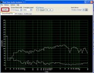
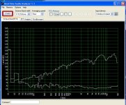
the measures: pink noise and white noise. the lower trace is the noise floor of my workshop (close to a window with road traffic)
And the sound; better than expected
but on glorious stereo they sound even better
haven't a stereo pair, but using the mock up 5 and 6 gets the thing working.
they arent the same size, and one is 1 Ohm (plus a resistor of another ohm) and the other 2.5 Ohms, but the perceived loudness is almost the same, and sound very alike.
Then, the stereo sound is impressive, tight focus, very transparent.
Still they lack bass, but in a manner that fool you into thinking the bass is there, so a drum kit sound pretty well.
seems to me that they will make a good desktop pair.
now it's time to think on a final design with a mini sub...
Now, the six mock up is working
It's a true epsilon of 15 x 25 Cm square, and 2.5 Ohms
the greater area has increased the bass response, together with a very high tension membrane.
the measures: pink noise and white noise. the lower trace is the noise floor of my workshop (close to a window with road traffic)
And the sound; better than expected
but on glorious stereo they sound even better
haven't a stereo pair, but using the mock up 5 and 6 gets the thing working.
they arent the same size, and one is 1 Ohm (plus a resistor of another ohm) and the other 2.5 Ohms, but the perceived loudness is almost the same, and sound very alike.
Then, the stereo sound is impressive, tight focus, very transparent.
Still they lack bass, but in a manner that fool you into thinking the bass is there, so a drum kit sound pretty well.
seems to me that they will make a good desktop pair.
now it's time to think on a final design with a mini sub...
Attachments
Very Cool.
My next little ESL's will be nearly the exact same size as your panels,so it is good to see your measurements.
What were the distances of your measurements from your panels?
Your second plot shows the typical response of a narrow panel in the Farfield similar to my first little panel.
As my little panel had a diagphram width of 8cm and an overall of 12cm.
My next panel will be about 50% wider and have a diagphram width of 11.5cm and an overall dimension of 15cm X 31.5cm.
I used my little 5.25" sony boxes for sub's and this worked very well in the nearfield for an average listening level and at 95 db this was quite loud for comfort. I have those plots posted in a recent thread here,
http://www.diyaudio.com/forums/plan...-more-questions-els-design-3.html#post2875836
http://www.diyaudio.com/forums/plan...-more-questions-els-design-3.html#post2883721
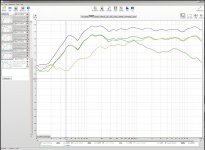
This is the last calibrated plot of the system before the panel failed on me (shorted out due to HV stator coating breakdown).
The db scale is a true calibrated Spl at 1 meter.
I also used some but very little EQ'ing to get the flat response in the farfield.
Mainly a little highend drop with the shelving EQ of -4.5db at 12Khz is all that I used and all else was flat on the panel except for an 80Hz cut to not saturate the step up transformer.
I am not trying to go Off Topic just trying to compare the results of similar sized panels is all.
As I too have been wanting to build some Mini Magnetic Planars as well.
I am wondering if it might be feasible to build some sort of stacked up diagphram's, AMT style, to handle the bass frequency's in a desktop design?
I would try it myself but I don't have enough magnets at the moment.
Cheers !!
jer
My next little ESL's will be nearly the exact same size as your panels,so it is good to see your measurements.
What were the distances of your measurements from your panels?
Your second plot shows the typical response of a narrow panel in the Farfield similar to my first little panel.
As my little panel had a diagphram width of 8cm and an overall of 12cm.
My next panel will be about 50% wider and have a diagphram width of 11.5cm and an overall dimension of 15cm X 31.5cm.
I used my little 5.25" sony boxes for sub's and this worked very well in the nearfield for an average listening level and at 95 db this was quite loud for comfort. I have those plots posted in a recent thread here,
http://www.diyaudio.com/forums/plan...-more-questions-els-design-3.html#post2875836
http://www.diyaudio.com/forums/plan...-more-questions-els-design-3.html#post2883721
This is the last calibrated plot of the system before the panel failed on me (shorted out due to HV stator coating breakdown).
The db scale is a true calibrated Spl at 1 meter.
I also used some but very little EQ'ing to get the flat response in the farfield.
Mainly a little highend drop with the shelving EQ of -4.5db at 12Khz is all that I used and all else was flat on the panel except for an 80Hz cut to not saturate the step up transformer.
I am not trying to go Off Topic just trying to compare the results of similar sized panels is all.
As I too have been wanting to build some Mini Magnetic Planars as well.
I am wondering if it might be feasible to build some sort of stacked up diagphram's, AMT style, to handle the bass frequency's in a desktop design?
I would try it myself but I don't have enough magnets at the moment.
Cheers !!
jer
Attachments
Last edited:
Measuring the power hungry speakers
I'm measuring the Number seven attempt. I expect it to be the first one of the stereo pair, so it is not a mockup.
I'm trying to measure of the power usage, but I'm not sure of my maths.
With a sinewave of 200 Hz, the rms V at the outputs of the amplifier is 12Volts, and with 1 Khz about 3V
Assuming the R =Z, the impedance is 2,2 Ohms
So, at 200hz the power is more or less 66W and at 1 Khz just 4W
Is this correct?
As allways, the pics later...
I'm measuring again, EQ off
With a sinewave of *100 Hz, the rms V is 12Volts, and with 200 about * 10V
From 500 Hz to 5Khz, 5,7 V
the impedance is 2,2 Ohms
So, at 100 *Hz the power is more or less 65W at 200Hz 45 W
From 500Hz to 5Khz *15Watts
The measures must be done fast, the heat build up is high at low freq.
Is this correct? Or the meter is faulty...
That is now becoming a difficult question.
What is providing the signals? How flat is its response supposed to be, into 2.2 Ohms?
The speakers are purely resistive, at those frequencies. So why would the voltage change when the frequency changes?
I am thinking that the amplifier in whatever is providing the signal might not be able to handle the 2.2 Ohms speaker impedance. To find out, you could try a much lower output voltage, such as 3 Volts (or as low as needed), at 100 Hz, and then try 200 Hz. If it stays at 3 V then try higher frequencies.
I am not sure what this testing is meant to test. The speaker impedance should not vary (unless heating the foil could lower the resistance by that much?). So you seem to be testing the ability of the amplifier to drive 2.2 Ohms at different frequencies. (But maybe, to be sure, you could quickly measure the resistance of the speaker, directly, with the meter, immediately after disconnecting the speaker, while it is still hot. [Simply turning off the amplifier's signal might not work as well, since there might be some residual output.])
But maybe I'm missing something, since the tension of the diaphragm might be making it more difficult to drive as the frequency is changed, which might make it "push back" against the amplifier's attempts. I'm not sure how that would work. Just guessing.
Maybe you should put a very-low-value resistor in series with the speaker cable (or measure the cable's resistance and use that), and measure both the current and the voltage, so you could see if the impedance is changing versus frequency. That should work, especially at these low frequencies, since the phase angle should stay the same for both the voltage and the current. (The current would be calculated from the voltage measured across the series resistance, I = V/R. Then the speaker's resistance or impedance would just be the voltage across the speaker divided by the calculated current.)
OR, it could be that the meter's response actually changes that much, versus frequency. But that just seems so unlikely. However, I could be wrong.
You could try sound card oscilloscope and spectrum analyzer software. But you would have to carefully design a resistor network to attenuate the signal while protecting the sound card input.
Later, it would be enlightening to keep the voltage constant and measure the sound pressure level.
You will probably also be very interested in finding out what voltage can be applied continuously, forever, without the speaker being damaged by heat (or posing a fire hazard), for the worst-case-heating frequency, so that you can determine the desired fuse rating and then fit a fuse on each one. It sounds like this might be extremely important.
The matter deserves further investigation.
when the power consumption increases, you can "see" clearly where the power goes, the diaphragm moves very hard.
I have taken the measures at full power, of course, so the amp surely is not working in its linear region.
The listening test are with a 15W amp, that seems ok for desktop use
The next test will be done with an amplifier that suffer less with this kind of load, but the data give an idea of the value of the fuse required.
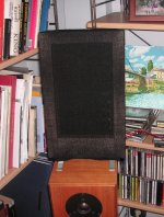
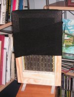
the last mockup?
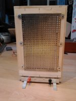
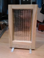
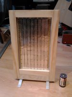
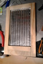
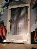
The pics;
not shown are the grille (still on the bench) and the rear cloth
As you can see, craftmanship is not my forte (I like to think it's lack of time) nor it is the photography with a phone.
but it works fine
as always happens, too late you discover a better way of doing things, this one, meant to be a definitive item must be the last mockup (again!)
the main problem still is how to maintain permanently the tension of the membrane...
The pics;
not shown are the grille (still on the bench) and the rear cloth
As you can see, craftmanship is not my forte (I like to think it's lack of time
) nor it is the photography with a phone.but it works fine
as always happens, too late you discover a better way of doing things, this one, meant to be a definitive item must be the last mockup (again!)
the main problem still is how to maintain permanently the tension of the membrane...
Attachments
I am vere sorry ! How can i delete 76 and 77 ? What is a url adress ? How can i insert picture ? Thomas.
like this
attachment
when you write a post, click on 'manage attachment'

moderation
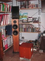
The sound of music
The sound of the mini planars
The speakers are almost complete. Now I'm listening to them.
As you can see on the first pic they are using the Tannoy R2 as stands. The Tannoys are also the reference, with a venerable Quad 405 for the brute force. Somwhere there are a musical fidelity xdac v3 for the finesse.
Not a top notch system but a very musical one.
How does it sound with the planars; well, it depends.
They sound clear ( maybe too much for my taste), crystal clear. The spl is more than enough, but need the subwoofer ( The Yamaha at the floor), together the sound is very good, coloured but engaging. Also a bit tiring, the high frecuency drill my ears at high volume. This also happens with the desktop loudspeakers I wanted to change for the mini planars, a pair of satellites using fountec ribbons (*Products_Fountek Electronics Co.,Ltd) , so I started to think is a problem of this kind of driver.
The problem is that they were not intended for standalone use, but as desktop speakers, and on this role the sound is very tiring. The frec. Response seems to be very strange. I'm using amarra software and usb dac amp (topping 30, 15 Watts*Topping TP30 Class T Digital Amplifier with USB-DAC 15 WPC 310-312) and are still fiddling with the parametric EQ to find a response filling the bass and taming the shouting heights. Still havent used the subwoofer.
So any help is welcome. Any way of tuning or tweaking the sound to sweeten the high frec...
The mini maggies doesn'lt seem to have this problem, and they have even less util surface than mines. So there must be a solution...
Maybe the problem are my own ears (I'm sligtly deaf with the age) but the problem don't arise with conventional drivers.
Any idea?
- Status
- This old topic is closed. If you want to reopen this topic, contact a moderator using the "Report Post" button.
- Home
- Loudspeakers
- Planars & Exotics
- Mini planar magnetic using neos