I just found this forum featuring a lot of Acoustat information and a dependable knowledge base. These threads are a "must read" for any owners of the many versions of this terrific speaker!
I've enjoyed my 2+2's since purchasing them used in the early 80's. Original configuration, non-medallion but label proudly states "Wired with Monster cable".
Year in, year out, never a problem. This is simply a superbly designed, conservatively manufactured piece of first class audio equipment. Everything I have done as a longtime, hardcore dedicated Hi-Fi hobbyist is to adequately feed these speakers.
With that in mind, allow me to add a tiny contributation, that of opinion and experience.
Do perform the "C Mod", regardless of possessing "Medallion" transformers. First, replace all of the high voltage disc caps on the voltage multiplier board.
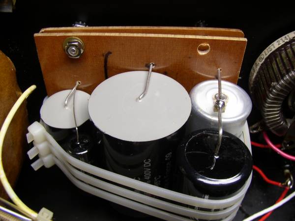
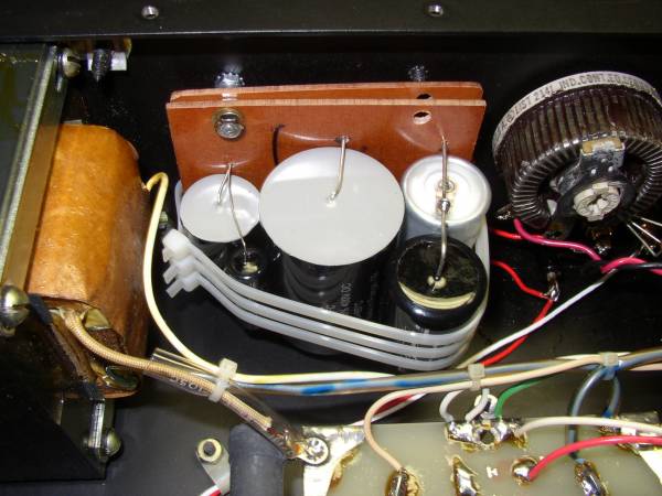
I see that some had questions pertaining to the physical mounting of the other components. The following pictures demonstrate the method I utilized to mount the capacitor bank (Solon, Mundorf, and Russian Teflon) on two, quarter inch thick phenolic boards.
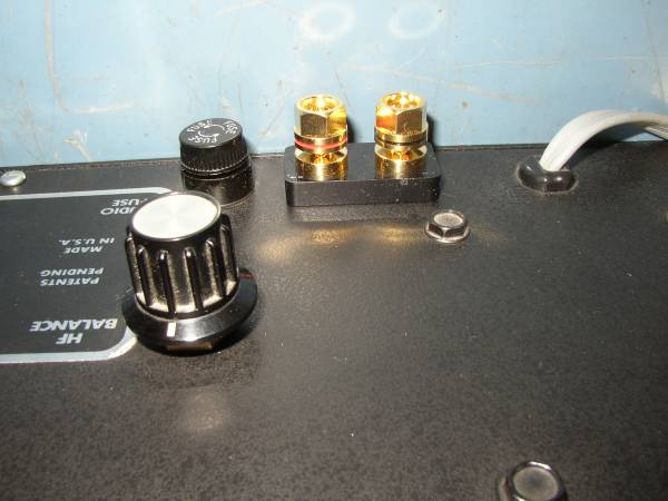
Mounting screws were added to the top and painted black to camouflage them. The only visible alteration to these beautiful speakers is the Vampire brand speaker binding posts replacing the original, pitiful binding posts. These were never up to the quality level of this classic.
This Photo shows the mounting of the added resistance and wiring changes utilizing Teflon insulated silver and (I think) DB brand Teflon insulated copper.
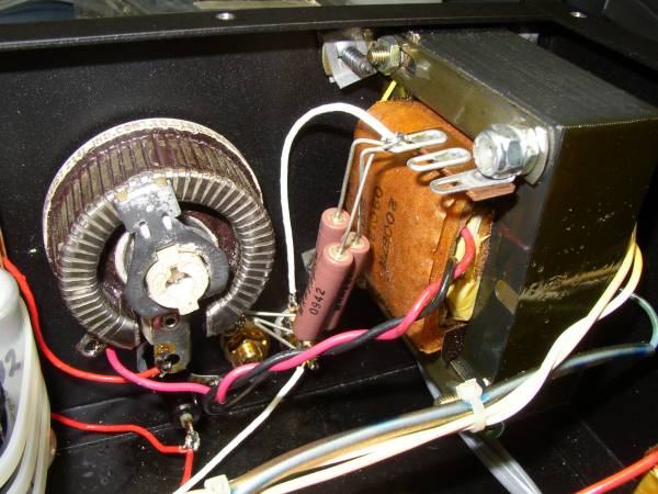
The Mills resistors, like the capacitor bank are paralleled, with each component measured and matched to achieve the most accurate left/right identity. Many will consider this useless or overkill but this is my hobby. It may seem senseless on a production run of 10000 units but this is the only pair I'm doing and to ignore this minute detail would, to me, be unthinkable.
The final result was neither small nor imagined. I will not go into the magical, musical changes that I heard. Be it the circuitry alterations or the replacement of very old electrolytic capacitors with new film types ...
Perform this Modification!!!
I've enjoyed my 2+2's since purchasing them used in the early 80's. Original configuration, non-medallion but label proudly states "Wired with Monster cable".
Year in, year out, never a problem. This is simply a superbly designed, conservatively manufactured piece of first class audio equipment. Everything I have done as a longtime, hardcore dedicated Hi-Fi hobbyist is to adequately feed these speakers.
With that in mind, allow me to add a tiny contributation, that of opinion and experience.
Do perform the "C Mod", regardless of possessing "Medallion" transformers. First, replace all of the high voltage disc caps on the voltage multiplier board.
I see that some had questions pertaining to the physical mounting of the other components. The following pictures demonstrate the method I utilized to mount the capacitor bank (Solon, Mundorf, and Russian Teflon) on two, quarter inch thick phenolic boards.
Mounting screws were added to the top and painted black to camouflage them. The only visible alteration to these beautiful speakers is the Vampire brand speaker binding posts replacing the original, pitiful binding posts. These were never up to the quality level of this classic.
This Photo shows the mounting of the added resistance and wiring changes utilizing Teflon insulated silver and (I think) DB brand Teflon insulated copper.
The Mills resistors, like the capacitor bank are paralleled, with each component measured and matched to achieve the most accurate left/right identity. Many will consider this useless or overkill but this is my hobby. It may seem senseless on a production run of 10000 units but this is the only pair I'm doing and to ignore this minute detail would, to me, be unthinkable.
The final result was neither small nor imagined. I will not go into the magical, musical changes that I heard. Be it the circuitry alterations or the replacement of very old electrolytic capacitors with new film types ...
Perform this Modification!!!
Poor stereo on my 1+1's
Dear all,
I own Acoustat 1+1 since 10 years and I love the sound and design.
But I'm not satisfied with the overall stereo image and sound stage.
As comparison I owe old magnepan 3 in an active configuration, which have less transparency and dynamics, but give a lot larger and deeper stereo stage.
In the upper frequency the sound of the Acoustat comes 'from the speaker' and not from behind them as with the Magnepan. It makes the listening a bit tiring. I would call this 'too much directivity in the upper mids'
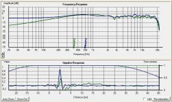
The curves herejoined represent the frequency response of both speakers in similar conditions.The 1+1 are blue and magnepan are green. Only the impulse response shows a significant difference : 1+1 shows larger dynamics, the facts are very impressive...
I do think that there is something wrong somewhere ...
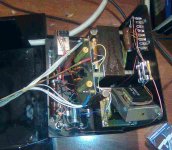
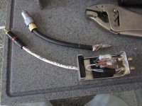
Here are also a photo of the interface.
Since this photo, I changed the electrolytic cap, the yellow caps, and the high tension ladder diodes and caps. It improved the transparency of the sound, but the stereo remains focused on the speakers.
Can you confirm to me the values of the high pass filter caps in the MK121 interface ?
Is there something I should do to improve things ?
Many thanks,
Mathieu
Note : preamp is a Perreau SM3, amps are EC AW180
Dear all,
I own Acoustat 1+1 since 10 years and I love the sound and design.
But I'm not satisfied with the overall stereo image and sound stage.
As comparison I owe old magnepan 3 in an active configuration, which have less transparency and dynamics, but give a lot larger and deeper stereo stage.
In the upper frequency the sound of the Acoustat comes 'from the speaker' and not from behind them as with the Magnepan. It makes the listening a bit tiring. I would call this 'too much directivity in the upper mids'
The curves herejoined represent the frequency response of both speakers in similar conditions.The 1+1 are blue and magnepan are green. Only the impulse response shows a significant difference : 1+1 shows larger dynamics, the facts are very impressive...
I do think that there is something wrong somewhere ...
Here are also a photo of the interface.
Since this photo, I changed the electrolytic cap, the yellow caps, and the high tension ladder diodes and caps. It improved the transparency of the sound, but the stereo remains focused on the speakers.
Can you confirm to me the values of the high pass filter caps in the MK121 interface ?
Is there something I should do to improve things ?
Many thanks,
Mathieu
Note : preamp is a Perreau SM3, amps are EC AW180
Attachments
First off, a special thanks to "AcoustatAnswerMan. Not only were you directly involved in the creation of this audio classic but your participation here will be responsible for its extended life!
Acoustannoy, I followed the "C Mod" pretty closely. The bank of capacitors shown is composed of:
(1) A Solon 47mfd. Film.
(2) A Solon 10mfd. Film.
(3) A Mundorf 1mfd, Film.
(4) A Mundorf .1mfd. and
(5) A .01mfd. Russian Teflon
Please keep in mind that there is resistance added along with a slight (but significant) circuit modification.
I'm hesitant to say this but I've never heard a Magnepan setup that I would prefer over these 'Stats.
It could be speaker location, supporting electronics, room acoustics, or just personal preference but these were very good before the update and magnitudes better afterward.
I highly recommend these changes!!
Good day Bobzilla,
Thanks for your accurate answer. I'm gonna do the change for caps.
I would then need some info about the resistors. I understand that you suppress the variable resistor, is that correct ?
Can you advise me a supplier for these, I cannot find any in Europe.
Thanks,
Mathieu
Thanks for your accurate answer. I'm gonna do the change for caps.
I would then need some info about the resistors. I understand that you suppress the variable resistor, is that correct ?
Can you advise me a supplier for these, I cannot find any in Europe.
Thanks,
Mathieu
Mathieu,
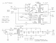
I used three Mills wirewound resistors in parallel to meet the required 10ohm as per this (Hafler designed??) modification:
http://www.audiocircuit.com/A-PDF/AA-Brands/A/Acoustat-ACO/MK-121-2_MED________-M-EN2-941-ACO.pdf
If by the term "suppress the variable resistor", you mean to place the resistance in series with the pot... yes, that is correct.
Bobzilla, the total value of the cap bank you use is about 58 microfarad.
The original MK121 interface is given for 230 microfarad (picture).
What is wrong ?
Hello Acoustannoy,
There is nothing wrong. The original MK121 interface did use 230uF as the schematic you posted shows.
But, the C-mod uses 57uF as shown in the attached schematic of the MK-121C interface.
See also the upgrade sheet Andy Szabo(aka AcoustatAnswerMan) posted some time ago that neatly summarizes several resistor network options when adding the ModC to your MK-121 interfaces.
Attachments
Yeahhh
Good ! Now I understood. Thanks bolserst, thanks bobzilla.
Factory was closed today, so I do not work, and could spend the whole day updating the interfaces, measuring and listening.
My goal is quite precise concerning the Acoustats : I owe them since more than 10 years. I love the sound, the dynamic, the transparency.
But I want to open their sound and to limit their directivity, which make them a little bit tiring and frustrating sometimes.
The model I have had already the medallion and Cmod performed. I just changed all the components for new and better ones, and cut the low frequencies thanks to a 12db/oct High pass passive filter between the preamp and power amp. An active sub is doing the job under 50Hz.
But,
I had the most impressive improvement today, through the addition of the cap as recommended on
Izzy Wizzy Audio
Izzy Wizzy Audio
(sketch herewith - the 0,01microfarad 5000V is a yelow polyester cap)
Modification is easy to do, and for the first time I had a significant improvement of the stereo image in the two directions : it is broader and deeper, the sound does not stick to the speakers as before ! Female voices are impressive.
1- I highly recommend this mod
2- I don't understand the technical reason
3- what can be done to go even further ? Does increasing the cap value makes sense ?
Mathieu
Attachments
Last edited:
Re: Yeahhh
Acoustannoy, glad you are getting better sound from the Acoustats.
For the Izzy Wizzy high voltage mod, I added a .022uF 6000 volt Wima polypropolene capacitor to the high voltage circuit in each interface. It had the same effect you described for your .01mfd 5000 volt mod.
I also replaced the 500 MegOhm resistor with a 20 MegOhm one in each interface. The speakers now play a little bit louder and seem to be more dynamic. I remember reading that this mod increases the high voltage to the panels.
The smaller interface cases on my 1+1 speakers do not have enough room for large capacitors such as the ones that Bobzilla used. So I used two Solen 28mfd polypropolene caps for a total of 56mfd. For a bypass cap, I used a .18mfd Jensen paper-in-oil cap. I prefer it over the stock .1mfd polystyrene bypass capacitor.
The improvement in sound was immediately obvious to my friends who are not into audio at all. They commented on the better sound even though I did not tell them that I had modified the interfaces. The speakers are much more relaxed to listen to. I hear more detail. The sound does not "stick" to the panels as much as before.
I also did these mods to a friend's Acoustat 2+2 interfaces. He was happily surprised.
A little bit of theory ?
Thanks Noelm for your interest !
Two day of listening confirm the improvement given by the additional parralel capacitor.
The result of this mod is so real and positive that I feel the need to go further now...
1 - Replacing the 500Mohm with a 20Mohm ? Looking at the circuitry it should'nt change a lot the value of the High Tension ... Adding a step to the high tension ladder is a safer way (done on my acoustat 1+1).
Pro => The high tension frame is loaded througgh the Tension ladder and the 500Mohm resistor, and acts as a capacitor. Reducing the value of the 500 Mohm capacitor will reduce the damping of the circuitry, not increase the HT level (if I'm right).
But reducing the damping result can provide a little bit 'quicker' impulse response, which could explain the feeling you have of a 'louder' sound
Con => On the other hand, reducing the value of the 500Mohm resistor from 500 to 20 will increase the intensity by a factor > 20x in case of short circuit between the high tension frame and the mylar film. It could definitively make a big hole in the film in case of too loud listening.
2 - The level of sensibility of the sound quality and 3D feeling, to the parrallel capacitor addition, and more generaly the sensibility of the Acoustat to the type of capacitor (polyester, polypropylen..), used in the HT side surprises me a lot. I seems to give a new direction about the possible progresses in reducting the directivity of the electrostatic pannels. I'm gonna make some more investigation in this direction.
3 - Can Acoustatanswerman give us a little help for understanding ?
A global understanding of the kinetic interface would help us I think.
For example, what is the way to calculate the low tension capacitor value (47microfarad,) ? This capacitor is loaded by a transformer, himself loaded by a 1ohm resistor plus the capiacitance of the pannels ? I wonder ...
Did Mr Jim Strickland release a complete theory on these interfaces ?
Many thanks,
Mathieu
For the Izzy Wizzy high voltage mod, I added a .022uF 6000 volt Wima polypropolene capacitor to the high voltage circuit in each interface. It had the same effect you described for your .01mfd 5000 volt mod.
I also replaced the 500 MegOhm resistor with a 20 MegOhm one in each interface. The speakers now play a little bit louder and seem to be more dynamic. I remember reading that this mod increases the high voltage to the panels.
noelm & Acoustannoy,
This topic has been covered before in the following thread.
The discussion did branch off to the addition of large value chokes in the HV feed line.
http://www.diyaudio.com/forums/planars-exotics/57310-high-voltage-supply-filtering.html
In general, the conclusion from my own experiments has been that the majority of the differences/improvements you hear from adding the 0.01uF cap and reducing the value of the 500Mohm resistor are due to the resulting increase in the bias charge on the diaphragm. This is most noticeable on older panels that have developed some leakage. Remember that the Acoustat panels have only a single contact point for charging the diaphragm rather than a ring all the way around the panel.
Also, be advised that the added 0.01uF capacitor charges to the full bias voltage and will store considerably more charge than the unmodified HV supply. So, be carefull and make sure the capacitors are discharged before performing any additional work on the supply.
I would rather another approach. The stock 500 meg resistor is as good a sounding one as you are ever likely to find. Rather than change it out for a smaller 20 meg unit add more stages to the multiplier to get the output voltage up. Two additional stages should do the trick, try that first. Best regards Moray James.
That`s very good that you not only liked the mod but can confirm it for others. The diaphragm coatinf on the Acoustat panel is so low that you really do not have to worry about a conductive ring around the panel the stock coating is very conductive as is and that is a very good reason to leave the high resistance (500 meg ohm) resistor in place to make sure that there is no current on the diaphragm to dopossible damage especiall with the panels being old and the dielectric oon the stator wires breaking down with age. Best regards Moray James.
I don't really understand why this mod would make a change in the sound, but if you like it, that's all that matters. (The time-constant of the 500-Mohm resistor combined with the panel's capacitance would suggest that additional filtering would not be necessary.) One negative aspect of this mod is that the power supply will stay charged much longer after removing power, so be sure to discharge it thoroughly before sticking your fingers in there. Increasing the value may be even better, but since I don't understand the mechanism at work here, I can't be sure. Do note that adding the capacitor after the 500-Mohm (instead of before as you have done) is NOT recommended, as some people have suggested. Doing so will violate the contant-charge principal that is the basis for the design, as well as increasing the possibility of panel-damaging arcing. Also, be sure that any capacitor used in this position is rated at least 5000 VDC.
sunday's music
Nice sunday morning, listening at the pianist Noel Lee and Baryton Bernard Kruysen, singing the Baudelaire poemes put in music by Henri Duparc. Heavens's music...
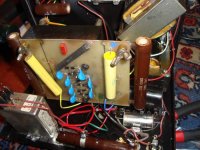
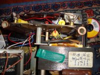
The old 1+1 never sounded so good in 10 years. Here are photos of the interfaces. You can see
- the modified 47mF cap (I kept the original 10mF and 0,1mF ones
- the additional HT ladder step (caps and diode were changed)
- the additional 0,01 mF/5kV cap.
The wiring is not very professional, and the variable resistors are burnt at some places...
a. I put also photos of the 'Active-passive' filter which is located between the preamp and the amp.
It is a 6db/oct on the photo, which was modified into a 12db/oct.
Such filters give astoning good results in terms of dynamics and transprency. I changed all my active filter stuff against this solution.
Design is done with help of the Micro-cap simulation software.
...To whom it may interest, I designed also such a 2way 12db/oct-18db/oct filter for my Magnepan IIIa, with incredible dynamic results, without any loss of information.
b. Now I would like to bring to the end the 1+1 improvements,
- internal wiring with the same cable brand as the one I use (precisely T.Labs RSC500)
- suppressing the variable resistor in the High frequ. filter
- testing MKP -polypropylen- caps on the HVoltage section
- testing values below 500Mohm for the HV resistor
...Moray can you see if you can find
- MKP or similar polypropylen 0,01uF 6kv resistors (x6). Is a higher value makes sense ?
- two 200Mohm and two 20Mohm HV resistors
- replacement for the 16ohm variable resistor into 2 fix resistors (13ohm and 3ohm) ?
Have a nice sunday,
Mathieu
Nice sunday morning, listening at the pianist Noel Lee and Baryton Bernard Kruysen, singing the Baudelaire poemes put in music by Henri Duparc. Heavens's music...
The old 1+1 never sounded so good in 10 years. Here are photos of the interfaces. You can see
- the modified 47mF cap (I kept the original 10mF and 0,1mF ones
- the additional HT ladder step (caps and diode were changed)
- the additional 0,01 mF/5kV cap.
The wiring is not very professional, and the variable resistors are burnt at some places...
a. I put also photos of the 'Active-passive' filter which is located between the preamp and the amp.
It is a 6db/oct on the photo, which was modified into a 12db/oct.
Such filters give astoning good results in terms of dynamics and transprency. I changed all my active filter stuff against this solution.
Design is done with help of the Micro-cap simulation software.
...To whom it may interest, I designed also such a 2way 12db/oct-18db/oct filter for my Magnepan IIIa, with incredible dynamic results, without any loss of information.
b. Now I would like to bring to the end the 1+1 improvements,
- internal wiring with the same cable brand as the one I use (precisely T.Labs RSC500)
- suppressing the variable resistor in the High frequ. filter
- testing MKP -polypropylen- caps on the HVoltage section
- testing values below 500Mohm for the HV resistor
...Moray can you see if you can find
- MKP or similar polypropylen 0,01uF 6kv resistors (x6). Is a higher value makes sense ?
- two 200Mohm and two 20Mohm HV resistors
- replacement for the 16ohm variable resistor into 2 fix resistors (13ohm and 3ohm) ?
Have a nice sunday,
Mathieu
Attachments
Last edited:
- Status
- This old topic is closed. If you want to reopen this topic, contact a moderator using the "Report Post" button.
- Home
- Loudspeakers
- Planars & Exotics
- Acoustat Mods