I own a Martin Logan Arius. I also notice that they put small pieces of see through plastic in the middle. However, I find that their treble sounds unnatural. I'm not sure if it has anything to do with these damping plastic pieces.
Wachara C.
I would agree with your opinion of the Arius treble sound. There are many possible contributors to the sound of the Arius panel including: thick diaphragm material, peaky transformer response, underdamped EQ of the midrange, crossover is less than an octave away from fundamental diaphragm sectional resonances. I tried removing the plastic damping sheets from a pair of ML speakers and found they sounded harsher than with them in place. At the time I did not own any measuring equipment, so I can not quantify the difference.
ML was pretty proud of the damping sheets. They described them in their brochure as:
"...advanced pressure compensation technology that permits tone shaping in the diaphragm of + or - 6dB without the use of an insertion loss crossover..."
http://www.martinlogan.com/pdf/brochures/brochure_aerius.pdf


What spacer thickness are you using now?
4mm för the bass panel (abt. 3.5mm in reality as I compress the panel a bit when mounting it) and 2mm for the mid/high section!
/R
Basspanel, 5kV bias, 1:80 :

Treble/tweeter-panel, 3kV bias, 1:40:

Both panels together:

It made a huge difference in bass and SPL capability when I changed my trafo setup!
Now using 4 pcs. 2x12V/2x115V in paralell/series, 0.33 Ohm equalising resistor on each primary winding and 1.5Ohm in series wing the "total" primary winding.
This is just a start, and values are sure to change when I measure impedance and start to experiment with the filters!
Roger
Treble/tweeter-panel, 3kV bias, 1:40:
Both panels together:
It made a huge difference in bass and SPL capability when I changed my trafo setup!
Now using 4 pcs. 2x12V/2x115V in paralell/series, 0.33 Ohm equalising resistor on each primary winding and 1.5Ohm in series wing the "total" primary winding.
This is just a start, and values are sure to change when I measure impedance and start to experiment with the filters!
Roger
Last edited:
Wachara: Volatge is abt. 5kV for the bass and 3kV for treble/tweeter.
My probe causes a voltage drop, so the voltage is probably a couple hundred volts higer in reality!
I dont find the basspanel harder to drive now with 4mm d/s, but it is hard to tell as the setup with EHT and audiotrafos have changed along the way!
For tests I'm using one off my GainClone amps with LM3875. It becomes an oscillator if I drive the speakers as a pure capacitance and need a series resistor to become stable!
Roger
Last edited:
After some problems with tape slipping, I finaly got the panels for one speaker mounted!
I hope to have some time today to hook them up and do a frequency sweep!
Hello SM7UYJ,
Very nice looking panels indeed!
Could you share some details concerning how you performed your measurements?
Are they averaged noise response, or a windowed impulse response?
Where was the mic placed? about how far away and how high relative to the midpoint of the panel?
Did you look at off-axis response at all to see how the bass and treble panels interacted with each other?
bolserst: I dont know if it's windowed or averaged, I cant find information abt. this!?
These measurements where made in my electronics lab, wich is way to small for these speakers, and I use the results mearly as a guide as to where to start!
The mic was placed abt. 0.7-1m from the panel and 1/3 up.
Off axis measurements where not made as I have no XO made so far.
From the sweeps I was thinking off using the bass panel up to 250Hz where the treble/tweeter-panel takes over.
Any sugestions off how to make the Xo for the two panels?
Roger
I dont know if it's windowed or averaged, I cant find information abt. this!?
These measurements where made in my electronics lab, wich is way to small for these speakers, and I use the results mearly as a guide as to where to start!
The mic was placed abt. 0.7-1m from the panel and 1/3 up.
Off axis measurements where not made as I have no XO made so far.
From the sweeps I was thinking off using the bass panel up to 250Hz where the treble/tweeter-panel takes over.
What software did you use to perform the measurements? We should be able to determine what type of measurement was taken based on the software.
With a panel of that size measurements at 1m distance will still be in the near field. I would suggest taking measurements at 2m - 3m or what ever your listening distance will be. You will find that the curves will slope downward at the low end as you move the microphone further from the panel. You will notice this also when listening to music, as you move away from the panel the bass will sound reduced in level. You will probably want to compensate for this in the crossover so the mid-bass response (100Hz-300Hz) sounds at proper level relative to the rest of the output.
The easiest way to crossover two separate panels is with an electronic crossover and then drive each panel with a separate amplifier. This avoids a lot of complications in the crossover design and will allow you to easily match the output of the bass and treble panels by changing the gain of the amplifiers.
The software used is Tombstone !
The speakers are so big, that I can olny measure nearfield in my lab.
When I get the electronics mounted I will do a more correct measurement in my living room!
My initial taught was to make the speakers active with built in filters and amplifiers, but passive makes tweaking different amps so much easier.
Roger

The software used is Tombstone !
The speakers are so big, that I can olny measure nearfield in my lab.
When I get the electronics mounted I will do a more correct measurement in my living room!
My initial taught was to make the speakers active with built in filters and amplifiers, but passive makes tweaking different amps so much easier.
I am not familiar with Tombstone, will have to check it out.
If you would like to try passive filtering, the first and easiest step is to LP the bass panels.
Based on the panel dimensions you have posted I would estimate the capacitance of your bass panels with D/S=4mm to by about 500pF.
So, for starters, try adding about 1Mohm resistance in series with the bass panel.
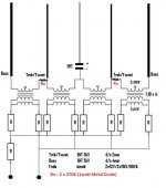
I would recommend splitting up the total resistance into four 270Kohm resistors to spread the required voltage drop and power dissipation. I generally use 1Watt Metal Oxide resistors for this purpose.
Placing the resistors symmetrically between the inner set of transformers driving the treble panel and the outer transformers also isolates the inter-winding capacitive load of the outer transformers from loading down the inner transformers. This will reduce the capacitive load the amplifier has to drive at high frequencies.
Measuring the bass panel with these resistors in place should show a roll off in frequencies above about 300Hz.
Attachments
Thank you for the input - very helpfull!
")
I was thinking off filtering the bass panel with as resistor but would have put the resistor on the output side off the transformer - will try your sugestion when I get home today!
Any sugestion on how to make a smart passive HP-/notch- filter to help tame the resonance at 45Hz?
Roger
I was thinking off filtering the bass panel with as resistor but would have put the resistor on the output side off the transformer - will try your sugestion when I get home today!
Any sugestion on how to make a smart passive HP-/notch- filter to help tame the resonance at 45Hz?
Roger


- Status
- This old topic is closed. If you want to reopen this topic, contact a moderator using the "Report Post" button.
- Home
- Loudspeakers
- Planars & Exotics
- My 2:nd ESL-attempt