Perhaps I should know better than to ask a question like this when I'm tired on a Friday night, and enjoying an end-of-week beverage, but I'm seeking insights into the role of stator insulation in ESL design and operation. There have been several threads on different types of insulation, and the effects they might have, but what is the real reason to insulate the stator?
For the moment let's assume we have another method in place to prevent anyone from simultaneously licking the two stators 😱. I'm focusing on the stator-diaphragm gap. If another design feature were in place to prevent the high resistance diaphragm from contacting each low resistance stator, would there be a need for insulation?
There have been some recent discussions about the use of fine netting to damp diaphragm resonances. If the netting were placed between the diaphragm and the stator so that the two couldn't come into contact, would that eliminate the need for insulated stators? Could we get away from concerns about high resistivity stator coatings and time constants and humidity sensitivity? What am I missing?
Few
well it not always that the diagraph hits the stator, the problem is conductivity of air! if im right air wil conduct and the spark can jump 1 mm with 3 Kv so 6 kv 2 mm etc, i mean without insulation most panels with 1 mm spacing wil arc everytime you listen music. wich sounds crap and also burns holes in ur mylar.
then you can either lower ur voltage and get lower SPL or increase stator distance wich wil do the same lower you SPL
then you can either lower ur voltage and get lower SPL or increase stator distance wich wil do the same lower you SPL
Don't forget the safety measure that you might come into contact with the stator while the music is playing. The zap can kill you.
Wachara C.
Wachara C.
And what about dust (conductive) coming between the unisolated stator and the Mylar.
That would make an arc even without music playing?!
Insulation is not that bad to sacrifice reliability and safety
That would make an arc even without music playing?!
Insulation is not that bad to sacrifice reliability and safety
Thanks for the replies. Wachara C., I didn't forget the safety issue. That's why I said "For the moment let's assume we have another method in place to prevent anyone from simultaneously licking the two stators."
I'm not sure I follow your logic WrineX. If you add insulation such that it prevents arcing (by dropping some of the voltage through the insulation instead of the gap), you end up with the same sensitivity reduction you would have gotten by reducing the bias voltage.
I guess I can see that a large amount of dust could form a bridge between the stator and the diaphragm so some form of dust cover could be used. Nonetheless, I'm left wondering if using fine netting to prevent diaphragm-stator contact might be a viable alternative to insulating coatings--especially if some builders end up wanting to add the netting to damp the diaphragm's fundamental resonance.
Few
i think it depends on the insulation properties. if an insulation of 0,5 mm will arc at 6000 just assuming here, it is at least higher then air, so when ur create 1 mm spacing with air only it will arc at 3000, using the insulation the conducting stator will be 0,5 mm further away but you can use twice the current, i thinks that would be win!. by the way o,5 mm is pretty thick for a insulation 🙂 but ok, in dream land we wnat conducting stator with a verry verry thin insulation but verr verry good , like rated 10000 or whatever. explaining stuff in english is not one of my favorites i think
but i have to check if doubling voltage is giving you the same spl as decreasing the spacer by half
but i have to check if doubling voltage is giving you the same spl as decreasing the spacer by half
well it not always that the diagraph hits the stator, the problem is conductivity of air! if im right air wil conduct and the spark can jump 1 mm with 3 Kv so 6 kv 2 mm etc, i mean without insulation most panels with 1 mm spacing wil arc everytime you listen music. wich sounds crap and also burns holes in ur mylar.
then you can either lower ur voltage and get lower SPL or increase stator distance wich wil do the same lower you SPL
You are 100% correct.
I just tried my ESL whose stator without insulation inside.
4000VDC and 2mm spacer,I see the spark. 😀
But the sound from ESL is really good,very transparent.
🙂 well go get some paint and paint it like 5 times 🙂 crappy job but hey no sparks
I will send the new stators to the car paint factory,it's better and not expensive.
4PCS of 300MM*1200MM double sides, cost 70USD.
I choose the color of dark blue,just like BMW. 😀
i think it depends on the insulation properties. if an insulation of 0,5 mm will arc at 6000 just assuming here, it is at least higher then air, so when ur create 1 mm spacing with air only it will arc at 3000, using the insulation the conducting stator will be 0,5 mm further away but you can use twice the current, i thinks that would be win!.
The problem is that in your example the 6000 V is what you're applying to the stator but you have to take into account the fact that the insulation and the air gap act as a voltage divider; some of the applied 6000 V drops across the insulation rather than the air gap so it is not experienced by the diaphragm. As a result you might be able to apply 6000 V to the insulated stator, compared to 3000 V for uninsulated panels, but that doesn't mean the diaphragm experiences a larger force in the 6000 V case.
but i have to check if doubling voltage is giving you the same spl as decreasing the spacer by half
Decreasing the air gap by half increases the sensitivity by a factor of four---it goes as the square of the distance.
Few
Perhaps I should know better than to ask a question like this when I'm tired on a Friday night, and enjoying an end-of-week beverage, but I'm seeking insights into the role of stator insulation in ESL design and operation. There have been several threads on different types of insulation, and the effects they might have, but what is the real reason to insulate the stator?
For the moment let's assume we have another method in place to prevent anyone from simultaneously licking the two stators 😱. I'm focusing on the stator-diaphragm gap. If another design feature were in place to prevent the high resistance diaphragm from contacting each low resistance stator, would there be a need for insulation?
There have been some recent discussions about the use of fine netting to damp diaphragm resonances. If the netting were placed between the diaphragm and the stator so that the two couldn't come into contact, would that eliminate the need for insulated stators? Could we get away from concerns about high resistivity stator coatings and time constants and humidity sensitivity? What am I missing?
Few
Uninsulated stators are not unheard of…QUAD did not use insulation on the tweeter-mid panel of their ESL57. They used heat shrunk film dust covers to keep the airgaps and stators clean. As long as people kept their amplifier power within the recommended range all is well. But, with the large solid state amplifiers available today, arcing is common.
But, to answer your question, in my opinion the main purpose for stator insulation is to avoid high current arcing; stator-to-diaphragm, and stator-to-stator. As long as you know what the maximum voltage you will be feeding the stators and the bias voltage you are putting on the diaphragm will not combine to exceed the breakdown voltage for air (roughly 4kV per mm) you can dispence with the insulation.
But be warned that the conductivity of air does increase with humidity, and once the air in the gap starts to ionize conductivity increases further as conduction starts and with no insulation to limit the current arcing occurs. I wouldn’t count on damping mesh on the inside surface of the stators to keep high current arcing from taking place. Something tells me that those pesky electrons will have no difficulty finding the holes in the mesh.
As others have mentioned, dust or sharp edges can significantly reduce the voltage at which arcing will occur. Wire stators are better than perforated sheet metal in this regard.
The main reason to not use insulation is to maximize the efficiency of the ESL.
But, with proper choice of insulation you lose little if any efficiency.
In fact, insulation allows you to run the bias and signal voltages higher without concern for arcing; thus actually improving efficiency.
PVC & Nylon are good insulation choices for ESL stators with high dielectric constant, and (for an insulator) lowish resistance. With either of these choices their resistance is so much lower than air, that essentially all of the bias voltage winds up in the gap, not across the insulation. If you increase the bias voltage to the point that the air in the gap starts ionizing and current flows in the bias circuit, then some voltage is dropped across the insulation. The insulation can be thought of as a ballast resistor that kind of self regulates the voltage in the gap to avoid arcing if ionization starts. (ie current flow drops voltage in the insulation which lowers voltage in the gap which will reduce ionization which reduces current flow, etc)
Also, because of the high dielectric constant, only 5% - 10% of the AC signal voltage is dropped across the insulation.
So, in the end, your gap width is essentially the distance between the diaphragm and the outside of the insulation, NOT the outside of the metal wire surface. My comparisons of wire test panels built with and without insulation confirm this.
Last edited:
Thanks for the reply Bolserst.
My intent wasn't to suggest that the mesh would prevent high current arcing from occurring. I meant that it would prevent diaphragm/stator contact. Also, if the diaphragm coating has high resistivity, shouldn't that limit the current associated with an arc? Of course ideally the ESLs would be operated in arc-free mode anyway, but I understand the need for safeguards.
I'm currently building wire-based ESLs so I'm not trying to go rogue. I was wrestling with some construction details/frustrations so I started to look at copper clad board as an interesting alternative that would still allow convenient segmentation. Insulating the board came to mind, and I couldn't help wondering if there might be alternatives to figuring out a way to coat the copper and worrying about the insulation not coating the sharp edges well. Perhaps coat first and perforate later...
In any case, thanks for the thoughtful response.
Few
I wouldn’t count on damping mesh on the inside surface of the stators to keep high current arcing from taking place. Something tells me that those pesky electrons will have no difficulty finding the holes in the mesh.
My intent wasn't to suggest that the mesh would prevent high current arcing from occurring. I meant that it would prevent diaphragm/stator contact. Also, if the diaphragm coating has high resistivity, shouldn't that limit the current associated with an arc? Of course ideally the ESLs would be operated in arc-free mode anyway, but I understand the need for safeguards.
I'm currently building wire-based ESLs so I'm not trying to go rogue. I was wrestling with some construction details/frustrations so I started to look at copper clad board as an interesting alternative that would still allow convenient segmentation. Insulating the board came to mind, and I couldn't help wondering if there might be alternatives to figuring out a way to coat the copper and worrying about the insulation not coating the sharp edges well. Perhaps coat first and perforate later...
In any case, thanks for the thoughtful response.
Few
Thanks for the reply Bolserst.
My intent wasn't to suggest that the mesh would prevent high current arcing from occurring. I meant that it would prevent diaphragm/stator contact. Also, if the diaphragm coating has high resistivity, shouldn't that limit the current associated with an arc? Of course ideally the ESLs would be operated in arc-free mode anyway, but I understand the need for safeguards.
Hello Few,
You are correct, using a resistance coating on the diaphragm does limit the amount of energy that will be dissipated in an arc between a stator and the diaphragm. In fact, this is probably a better solution to protection from diaphragm-to-stator arcing than the mesh is.
However, even with high resistance coating, you are still left with the other problem of arcing stator-to-stator. I experienced this a lot when running test panels built with uncoated perforated sheet metal and high resistance coating on the diaphragm. At first I thought the arcing was coating-to-stator, and I could see many holes punched thru the diaphragm. But, with the diaphragm completely removed and the stators reassembled, the arcing persisted...stator-to-stator. Cranking the air conditioner to lower the humidity in the room helped reduce the arcing tendency.
I'm currently building wire-based ESLs so I'm not trying to go rogue. I was wrestling with some construction details/frustrations so I started to look at copper clad board as an interesting alternative that would still allow convenient segmentation. Insulating the board came to mind, and I couldn't help wondering if there might be alternatives to figuring out a way to coat the copper and worrying about the insulation not coating the sharp edges well. Perhaps coat first and perforate later...
Few
You might check out Roger Sanders US patent application 10697392 for coating copper clad stator boards.
Encapsulated composite electrostatic ... - Google Patent Search
Essentially it looks like he etches the copper away from the areas he is going to put the openings in the stator so the edge of the copper traces are now on a flat surface rather than at the edge of the opening thru the stator.
I have not tried this myself but looks like a logical solution.
If you decide to give it a try, be sure to report back with your results.
Personally I've always been turned away by the thought of having to drill all those holes in the copper clad boards. I wonder what one of those PCboard etching companies like ExpressPCB - Free PCB layout software - Low cost circuit boards - Top quality PCB manufacturing would think if I submitted a board with all those holes to be drilled? 😀
Hi,
every PC-board manufacturer has the knowledge and capabilities to manufacture such a device. To get a patent granted on such a common technique makes one wonder what else might be patentable, maybe a car´s wheels??
Patent 4,533,794 granted to Mr. Beveridge in 1985 deals with the same issue. The only difference beeing the use of Nylon as coating instead of a second layer of PCB. Manufacture of the base layer and the conductive layer is exactly the same as with Sander´s.
Anyway You can simply send a board manufacturer Your layout and they will make it for You. You can even choose different thickness for the base material layers. FR-4 epoxy is well suited from its electrical parameters.
The only drawbacks are a restriction to rather small sizes (around 500mm maximum length) and a rather low mechanical stability.
jauu
Calvin
Hi,
every PC-board manufacturer has the knowledge and capabilities to manufacture such a device. To get a patent granted on such a common technique makes one wonder what else might be patentable, maybe a car´s wheels??
Patent 4,533,794 granted to Mr. Beveridge in 1985 deals with the same issue. The only difference beeing the use of Nylon as coating instead of a second layer of PCB. Manufacture of the base layer and the conductive layer is exactly the same as with Sander´s.
Anyway You can simply send a board manufacturer Your layout and they will make it for You. You can even choose different thickness for the base material layers. FR-4 epoxy is well suited from its electrical parameters.
The only drawbacks are a restriction to rather small sizes (around 500mm maximum length) and a rather low mechanical stability.
jauu
Calvin
Calvin,
Thanks for pointing out the Beveridge patent. I had not stumbled on that one before. Sure looks like the exact same idea(keeping the copper layer away from the edges of the holes) that Sander's put an application in for. But, his is still just an application...no patent granted.
Have you built panels with this PCB technique? How did cost compare to other methods?
Hi Bolsert,
i made some prototypes months ago.
In the picture you can see, how precise the drills and the copper layer is made.
The glance in the picture comes from the transparent isolation coating. This is a very specific one, it needs to dry under UV light. The advantage is that this coating can be applied in one run, building up to 0,2mm layer. As you can see it covers the copper layer perfectly and most important, it do not run into the holes, which are just 2mm in diameter.
In addition you can see that this stator has been segmented. The picture shows the border from one segment to the other
The board size has been 400x200mm and one board was about 20 Euro
Capaciti
Attachments

Hi Bolsert,
i made some prototypes months ago.
In the picture you can see, how precise the drills and the copper layer is made.
The glance in the picture comes from the transparent isolation coating. This is a very specific one, it needs to dry under UV light. The advantage is that this coating can be applied in one run, building up to 0,2mm layer. As you can see it covers the copper layer perfectly and most important, it do not run into the holes, which are just 2mm in diameter.
In addition you can see that this stator has been segmented. The picture shows the border from one segment to the other
The board size has been 400x200mm and one board was about 20 Euro
Capaciti
Thanks for the picture, Capaciti.
Very nice!
Most interesting geometry with alternating copper trace spikes in between the two sections.
So for one complete panel you would need 8 of the 400x200mm boards = 160 Euros. Expensive compared to wire stators, but not as much as I had thought.
The coating, is it a standard option that PCB manufacturers use? or is it something proprietary that you are developing for best ESL stator efficiency and reliability.
Patent 4,533,794 granted to Mr. Beveridge in 1985 deals with the same issue. The only difference beeing the use of Nylon as coating instead of a second layer of PCB. Manufacture of the base layer and the conductive layer is exactly the same as with Sander´s.
jauu
Calvin
I found this old thread concerning the Beveridge PCB stators.
http://www.diyaudio.com/forums/planars-exotics/51103-harold-beveridge-esls-2.html#post720289
Interesting that the PCB stators tended to eat away the low resistance metalized coating on the diaphragm.
I wonder if you would have the same issue when using a high resistance coating?
Very interesting posts, guys. Thanks very much.
Part of my interest stems from a recent check into the old standby----McMaster-Carr:
I had already allowed myself to be distracted by some online diy CNC router pages so when I put two and two together I got :
1) Eureka! $28 per board is pretty cheap, especially since you'd only need four for good-sized stereo ESL panels!
and
2) For only ~$1500 and lots of work I can build my own CNC router to drill all those holes! Too bad $1500 + time + board costs isn't so cheap anymore. I'm sure I could come up with other fun things to do with a large CNC router, though...
In any case, I'm glad to see this thread has taken such an interesting turn.
Few
Part of my interest stems from a recent check into the old standby----McMaster-Carr:
Grade G-10/FR4 Copper-Clad Garolite Sheet Clad on One Side, 1/32" Thick, 24" X 36" (610 mm x 910.4 mm): In stock at $28.01 Each
I had already allowed myself to be distracted by some online diy CNC router pages so when I put two and two together I got :
1) Eureka! $28 per board is pretty cheap, especially since you'd only need four for good-sized stereo ESL panels!
and
2) For only ~$1500 and lots of work I can build my own CNC router to drill all those holes! Too bad $1500 + time + board costs isn't so cheap anymore. I'm sure I could come up with other fun things to do with a large CNC router, though...
In any case, I'm glad to see this thread has taken such an interesting turn.
Few
Wow, talking about a DIY CNC machine, huh?
How about mine? 🙂
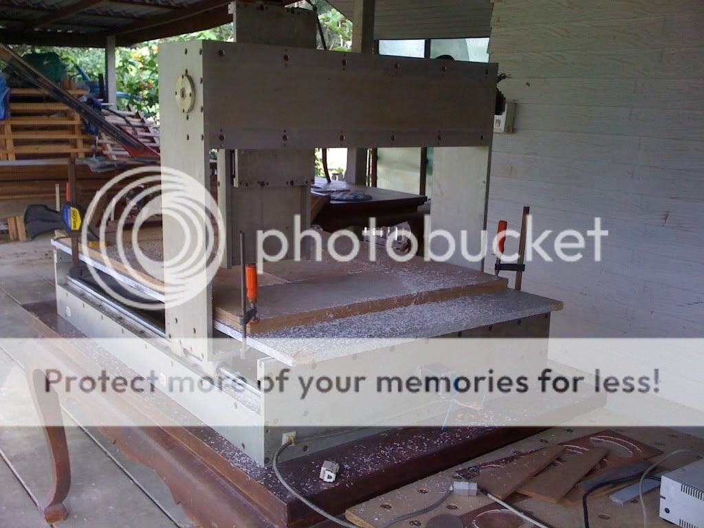
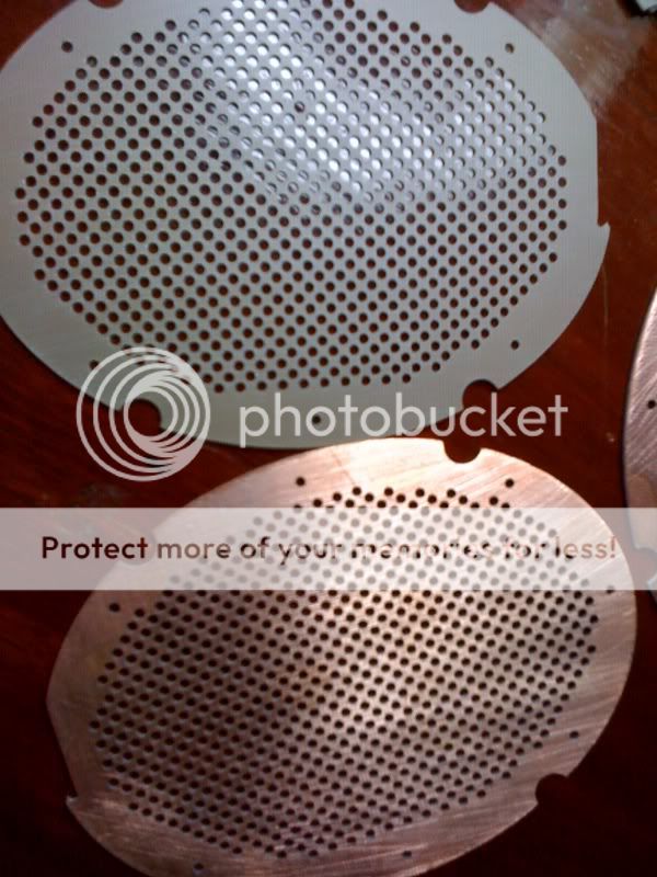
I used it to make the stators and spacers for my headphone. The material is 1 mm thick PCB. The holes are 2 mm. 🙂
Wachara C.
How about mine? 🙂
I used it to make the stators and spacers for my headphone. The material is 1 mm thick PCB. The holes are 2 mm. 🙂
Wachara C.
- Status
- Not open for further replies.
- Home
- Loudspeakers
- Planars & Exotics
- Role of ESL stator insulation?