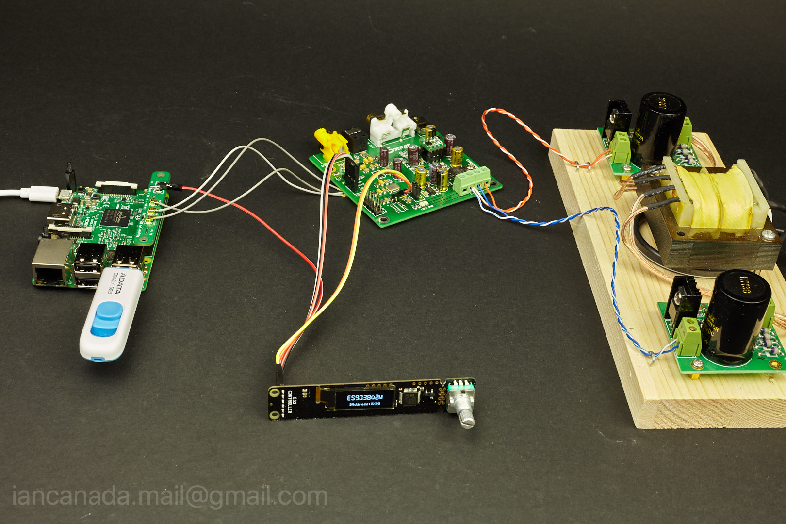
Some off topic testing: Ian ESS controller works with third party ESS9038Q2M DAC
I bought this ES9038Q2M DAC last year, just want to confirm my ESS controller works for third party ESS DACs.
Yes, it works.
This DAC was fine. The only two issues I had with my RaspberryPi 3 are:
1. It doesn't support 44.1KHz 16bit format, got big noise for this format.
2. It doesn't play DoP music correctly, the sound was just like kind of water flow( maybe the version is too old).
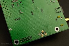
With my ESS controller, all above issues are fixed. DAC chip-id was recognized as ES9038Q2M. It plays 44.1KHz 16bit music nicely, as well as all other formats. The DoP was also been enables and plays without any problem.
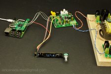
Please see pictures for configuration details.
Some experience to share:
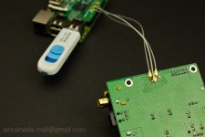
1. u.fl coaxial cables are tested much better than regular jumper wires for input signals. One of the pictures shows how to mount u.fl socket at bottom side of the DAC PCB.
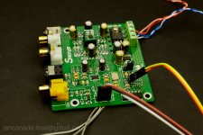
2. The on-board MCU has to be removed in order to use external ESS controller. Two I2C pins can be soldered right on top of the pull-up resistors.
3. When I replace the original OP with OPA1622, I got some improvement on sound quality. It can also drive my Sennheiser 300ohm headphone.
Ian
ESScontroller2 by Ian, on Flickr
I bought this ES9038Q2M DAC last year, just want to confirm my ESS controller works for third party ESS DACs.
Yes, it works.
This DAC was fine. The only two issues I had with my RaspberryPi 3 are:
1. It doesn't support 44.1KHz 16bit format, got big noise for this format.
2. It doesn't play DoP music correctly, the sound was just like kind of water flow( maybe the version is too old).
With my ESS controller, all above issues are fixed. DAC chip-id was recognized as ES9038Q2M. It plays 44.1KHz 16bit music nicely, as well as all other formats. The DoP was also been enables and plays without any problem.
Please see pictures for configuration details.
Some experience to share:
1. u.fl coaxial cables are tested much better than regular jumper wires for input signals. One of the pictures shows how to mount u.fl socket at bottom side of the DAC PCB.
2. The on-board MCU has to be removed in order to use external ESS controller. Two I2C pins can be soldered right on top of the pull-up resistors.
3. When I replace the original OP with OPA1622, I got some improvement on sound quality. It can also drive my Sennheiser 300ohm headphone.
Ian
ESScontroller2 by Ian, on Flickr
Attachments
Last edited:
Very nice little controller!
I see that you have also routed the I2S signals from the dac board to the controller board. Why is that? Is your controller monitoring these lines to determine bit depth / sampling rate?
Thanks Dimdim,
Yes, I designed a built-in music format analyzer in the ARM processor.
To me, this is not just something nice to have. I really need it to run ESS DACs at higher performance.
1. With this true signal format analyzer, precision control can be performed.
Sample rate, clock frequencies, X*Fs, date length, PCM/DSD/DoP format....All those information can be taken into consideration at same time and at real time to decide the most optimized DAC settings.
2. Make it possible to run ESS DACs at synchronized mode
Sound quality will get big improved if ESS DAC is running at sync mode. However, under sync mode, internal DPLL will be in "free wheel" state. And the MCLK is also not fixed at given frequency. No any useful information can be provided from internal registers. So in this case, have to do real signal monitoring to get music information,
3.Make it possible to silence the I2C communication between ESS DAC and controller while music is playing.
Otherwise it has to access ESS internal registers over and over to get some music information(still can not cover sync mode).
Ian
Last edited:
Thanks Dimdim,
Yes, I designed a built-in music format analyzer in the ARM processor.
To me, this is not just something nice to have. I really need it to run ESS DACs at higher performance.
1. With this true signal format analyzer, precision control can be performed.
Sample rate, clock frequencies, X*Fs, date length, PCM/DSD/DoP format....All those information can be taken into consideration at same time and at real time to decide the most optimized DAC settings.
2. Make it possible to run ESS DACs at synchronized mode
Sound quality will get big improved if ESS DAC is running at sync mode. However, under sync mode, internal DPLL will be in "free wheel" state. And the MCLK is also not fixed at given frequency. Without this real monitoring format information, no any useful information can be provided from internal registers in this case.
3.Make it possible to silence the I2C communication between ESS DAC and controller while music is playing.
Otherwise it has to access ESS internal registers over and over to get some music information(still can not cover sync mode).
Ian
Hi Ian,
I currently have a BII running with some Arduino code and display to control the DAC settings manually. The output stage is currently the NTD1. I'd like to try that controller of yours instead of the Arduino stuff. I guess I also need to have the RPi III and the controller HAT? Would it support automatic PCM and DSD switchover or need to use DoP?
Thanks
Do
Ian, awesome job with the u.fl sockets! Could you please share some information about how you managed to solder them to the board, as there are no pads.1. u.fl coaxial cables are tested much better than regular jumper wires for input signals. One of the pictures shows how to mount u.fl socket at bottom side of the DAC PCB.
Also, how did you connect the ground to sockets?
Ian, awesome job with the u.fl sockets! Could you please share some information about how you managed to solder them to the board, as there are no pads.
Also, how did you connect the ground to sockets?
@nielsek
Scratch the solder mask (green paint) under the GND pads of the u.fl socket. Solder GND pads of the u.fl socket to the ground plate of PCB with signal pad facing to the signal pin. Solder the signal pad of u.fl socket to the signal pin.
Do the same to all three u.fl sockets.
Regards,
Ian
Hi Ian,
I currently have a BII running with some Arduino code and display to control the DAC settings manually. The output stage is currently the NTD1. I'd like to try that controller of yours instead of the Arduino stuff. I guess I also need to have the RPi III and the controller HAT? Would it support automatic PCM and DSD switchover or need to use DoP?
Thanks
Do
Hi pinnocchio,
Yes, it's possible to support your BII. This ESS controller works either as RPi HAT or as independent driver. So the configuration would be very flexible and totally up to your application.
It supports PCM/DSD switchover, as well as DoP if your system is not capable for native DSD output.
Ian
@nielsek
Scratch the solder mask (green paint) under the GND pads of the u.fl socket. Solder GND pads of the u.fl socket to the ground plate of PCB with signal pad facing to the signal pin. Solder the signal pad of u.fl socket to the signal pin.
Do the same to all three u.fl sockets.
Regards,
Ian
@nielsek
Hope this picture can show you how to solder u.fl sockets to this ES9038Q2M PCB.
Regards,
Ian
Attachments
For audiophiles, this is the much better configuration.
The nice thing is that, with the IsolatorPi, the ESS controller becomes an isolated controller!
No longer having any electronic connection between the controller and ESS DAC. As well as the ground.
I don't like a noisy MCU to be integrated in a DAC board, that's one of the most important reason I design this independent ESS controller.
ESScontroller5 by Ian, on Flickr
Ian
Last edited:
IS FIFO function integrated in the DSD/I2S DAC HAT?
All my ESS DAC HATs are pure DAC. They don't have any other digital logic integrated on board.
Maybe just kind of audiophile's thoughts
") .
.Regards,
Ian
Hi Ian,
Do you know if this will be compatible with Roon from Roon Labs? I previously was using Moode but switched to Roon for the multi-room capability and especially the library handling. I'm also re-sampling everything to DSD 256 on my main DAC. Other DACs are format native.
Thanks
Do
Do you know if this will be compatible with Roon from Roon Labs? I previously was using Moode but switched to Roon for the multi-room capability and especially the library handling. I'm also re-sampling everything to DSD 256 on my main DAC. Other DACs are format native.
Thanks
Do
Hi Ian,
Do you know if this will be compatible with Roon from Roon Labs? I previously was using Moode but switched to Roon for the multi-room capability and especially the library handling. I'm also re-sampling everything to DSD 256 on my main DAC. Other DACs are format native.
Thanks
Do
Hi Do,
By default, my design works at hardware mode. So, theoretically can work with any software.
PCM/native DSD/DoP are all capable now. I don't see any problem to work with your new Roon software, as long as it can output those formats.
Regards,
Ian
I 2nd that sentiment. This looks like a neat package and could be enclosed however the user chooses. Maybe an option for a bigger display? I like it.Can't wait for your release of the whole setup, Ian.
Sounds really simple, never thought of that. Thanks, will give it a try!@nielsek
Scratch the solder mask (green paint) under the GND pads of the u.fl socket. Solder GND pads of the u.fl socket to the ground plate of PCB with signal pad facing to the signal pin. Solder the signal pad of u.fl socket to the signal pin.
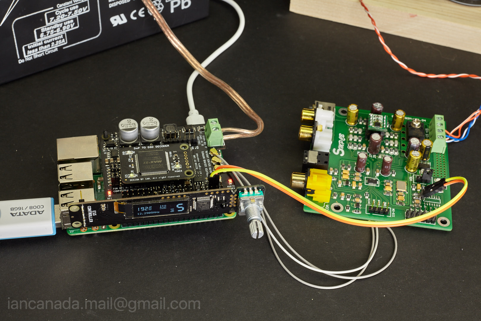
Dimensions of ES9018K2M / ES9028Q2M / ES9038Q2M DAC HAT
ES9038Q2MHATDimensions by Ian, on Flickr
Ian
ES9038Q2MHATDimensions by Ian, on Flickr
Ian
All my ESS DAC HATs are pure DAC. They don't have any other digital logic integrated on board.
Maybe just kind of audiophile's thoughts
Regards,
Ian
It's a pity. If the reclock module can be connected directly to a input terminal of DA chip, theoretically there will be almost no jitter in the digital circuit, and if the reclock module can be integrated with DA chip, the clock signal can be very close to provide the DA chip without the clock jiiter. I think this is the closest to perfect digital circuit design?
- Home
- Source & Line
- PC Based
- ES9018K2M, ES9028Q2M, 9038Q2M DSD/I2S DAC HATs for Raspberry Pi