I've been considering exactly how to answer your questions. I finally decided that an in-depth tutorial on filter types and filter orders was far too much for a forum reply, so I decided to simply summarize. The following is generally true, but there are many specific exceptions:This brings me to my somewhat hazy grasp of filters! I know that a particular filter order is related to "the slope" in terms of dB/octave. I also know (I think) that an Nth-order filter can only be realised with at least N filter taps in an FIR filter. I also have some inkling that it is related to the highest exponent in the frequency response expression. It may also have something to do with Laplace transforms and transfer functions but I've erased those horrible memories from my brain over the years. The filter order is also related to the number of delay elements in an IIR filter.
1. The filter order is the highest-valued exponent in the transfer function that describes the filter.
2. The order of the denominator of an IIR filter has far different effect upon the filter response than does the numerator order of a FIR filter.
3. For IIR filters, digital or analog, assuming "typical" filters in which the numerator order is less than or equal to the denominator order (and purposely avoiding filters with resonant sections, such as analog elliptic or Chebyshev filters, and any filters in which roots of the numerator polynomial cancel roots of the denominator polynomial), there is a strict relationship between the filter order and the maximum slope of the transition band(s): 6 dB/octave per order. Note that this may be divided between multiple transition bands -- for example, a 2nd order bandpass filter will have 6 dB/octave slopes in each of two transition bands.
3. There is absolutely no general statement that can be made about the order of an IIR filter and the shape of its impulse response, except that it is infinite in duration.
4. For FIR filters, the coefficients are the impulse response. This means that the frequency response of an FIR filter is the Fourier Transform of its coefficients. And FIR filters that are selective at low frequencies must have higher order than FIR filters that are selective at high frequencies, even if the shape of their response is otherwise the same, simply because low frequency waveforms have longer periods than high frequency waveforms.
5. There is absolutely no general statement that can be made about the order of an FIR filter and the slope of its transition band.
Basically, and I don't mean to sound flippant; it's because we live in an analog world. It is very easy to implement digital filters with amazing characteristics, but beyond a certain point it just becomes "fun with numbers". An example of this is one of the subjects of this thread -- the fact that extremely steep linear phase digital filters exhibit pre-ring. Even though such filters are mathematically perfect, in our analog world they sound very unnatural.And then there's the relationship between digital filters and analogue. I was tremendously excited when I found that I could create a filter with any frequency and phase response I wanted, even linear phase, using the FFT and windowing. Why, then, I thought, would anyone want to emulate analogue filters? I'm still wondering about that.
Digital filtering is a field unto itself. However, in the context of your question, a digital FIR implementation of a classical analog filter is simply a way of approximating the response of that analog filter.People seem to stick with integer even values for the order, and they still talk about Butterworth, Bessel etc. What is the relationship between analogue filtering, and digital FIR filtering?
Frankly, and again, I do not mean to sound flippant; it's a little of both.Are analogue filter responses in some way fundamentally good and pure, and therefore it is natural that they are emulated digitally by most people, or are people simply sticking with what they know?
Be very careful here! You have now introduced yet another definition of "order", one that has no relationship whatsoever to the IIR "denominator order" and FIR "numerator order" discussed above. It would literally take an infinite order FIR or IIR filter to implement a 2nd order Gaussian shape, though that can be reduced to more manageable values by relaxing some constraints.I like the idea of the Gaussian filter. But to make a Gaussian-derived Nth order filter, you simply replace '2' with 'N'. It seems kind of arbitrary, somehow.
Last edited:
New FIR_Lab version here.Does this mean that you are not adjusting the order as such? I'm thinking that varying the width adjusts the resulting filter's cutoff frequency, but doesn't change the order. Sinc is presumably the equivalent of a brick wall filter i.e. infinite order, and the pure Gaussian is 2nd order..?
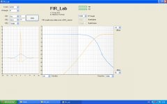
Variable FIR length. The transition band width decreases with the FIR gets longer. Due to the log frequency scale, the net effect is a crossover slope that's massively increasing with the FIR length.
Three different elements (Sinc, Gauss, Triangle) can be combined at will. Each can get bypassed (select Rectangle instead).
The Sinc parameter allows a direct crossover frequency control. This happens in a constant transition band width. Due to the log frequency scale, the net effect is a crossover slope that's massively increasing with the crossover frequency.
When using an integer for the Sinc parameter, the FIR nominal crossover frequency gets synchronized to the sampling frequency. In such case, you will observe patterns of FIR coefficients equal to zero.
The Gauss element and Gauss parameter help controlling the preshoot/ringing. Unfortunately, there are effects on the crossover frequency, and effects on the crossover slopes in the transition band. When the crossover is mainly governed by the Gauss element, the complementary highpass selectivity degenerates to a 2nd-order. This sets a practical limit to the idea of using the Gauss element for shortening the preshoot/ringing.
The Triangle element is there as optional element, for ensuring a true-zero end-window. When activating the Triangle element, the crossover slopes get more more symmetric, albeit with reduced slopes.
The FIR coefficients are written into a "FIR_Lab.txt" file on the hard disk, in the C:\ drive root.
Sorry for the "fur" that's becoming annoying when using large FIRs. I've got no time investigating the FFT buffers boundary effects (see former post).
Apart the "fur" effect, I'm pretty happy with FIR_Lab now. I like the no-nonsense approach, concentrating on the physical reality of the FIR instead of trying to emulate all sorts of things that a FIR is not.
Like you I am in search of a simple, physical, intuitive way to inject the meaning of a "slope" into FIR_Lab. A possibility is to add a second parameter to the Sinc element, bringing some short term "warping" in proportion to the nominal crossover frequency. Say a 10% frequency modulation with a certain profile over time, within the FIR. Which profile ?
Another possibility is to depart from the Sinc element. Instead of basing on 3 elements (Sinc, Gauss, Triangle), one could add a 4th element natively providing a natural transition band width control, proportional to the crossover frequency. Considering the nature of a FIR, it's not easy to identify such 4th element. Any idea welcome. Would be interesting to analytically compute the asymptotic behavior (the slope) of FFT-defined lowpass filters, linear-phase. Computing this properly may lead to mathematically expressing conditions that must be satisfied regarding the impulse response, easing the FIR design.
Attachments
Last edited:
It's not the first time I'm designing and programming a two-channel FFT analyzer. That one definitely has the taste of carrying a bug in the FFT buffers boundaries. Look how the "fur" increases with the FIR length.If you allow me to comment on that, I think that the 'fur' you and CuTop were talking about comes actually from the white noise sequence. Such a sequence of finite length can not be perfectly white. Actually, the longer it is, the 'whiter' it is as well. So in other words, there are spikes on your output signal because the spikes were originally present on your input signal.
In such two-channel analyzer, the more random your test signal, the less "fur" on the Bode plot. The two-channel analyzer gets very happy to have energy everywhere (at all frequency bins). He needs this for computing the out/in ratios in complex numbers, which is the Bode plot actually.
The two-channel FFT analyzer reality and practice is thus quite opposite to what you say. You will get a lot of fur "fur" if you feed it with a sinus. With a sinus, energy is missing in many frequency bins, and the out/in computation gets corrupt by noise in many frequency bins.
It's not the first time I'm designing and programming a two-channel FFT analyzer. That one definitely has the taste of carrying a bug in the FFT buffers boundaries. Look how the "fur" increases with the FIR length.
In such two-channel analyzer, the more random your test signal, the less "fur" on the Bode plot. The two-channel analyzer gets very happy to have energy everywhere (at all frequency bins). He needs this for computing the out/in ratios in complex numbers, which is the Bode plot actually.
The two-channel FFT analyzer reality and practice is thus quite opposite to what you say. You will get a lot of fur "fur" if you feed it with a sinus. With a sinus, energy is missing in many frequency bins, and the out/in computation gets corrupt by noise in many frequency bins.
First thing I'd like to say is that I'm coming in peace to praise your work like I'd praise anyone's sincere effort.
Second thing is that I never mentioned a sine anywhere in my previous post. Now talking about analyzing a sine with fft, you don't get 'fur' but you get the side lobes of the window you have selected.
This happens because when you are analyzing a signal, you must split it into portions, and the fact of slicing the signal is what is creating these lobes.
You know there are several kinds of windows, and all of them are a compromise of frequency selectivity (main lobe width) and side lobes level.
If you just split the signal, then you're actually applying a rectangular window. This has excellent frequency selectivity but high lateral lobes (-13 dB). The 'fur' you observe is nothing about noise corruption, it's just a property of your window and you get the same 'fur' even if you're computing with 1024 bits of precision.
Now coming back to the original topic, based on your screenshots it seemed that there were less spikes with longer fft. Apologies if this is not actually the behavior you have observed.
Finally, if your application is happy with displaying the frequency response corresponding to a computed impulse response, I'd suggest to forget about the fft and just compute the Fourier transform in plain.
I said longer FIR. Not longer FFT. Try yourself and you'll see there is a bug I still need to correct in FIR_Lab. By experience I know that once the bug will be gone, the "fur" won't increase when we increase the FIR length.The 'fur' you observe is nothing about noise corruption, it's just a property of your window and you get the same 'fur' even if you're computing with 1024 bits of precision. Now coming back to the original topic, based on your screenshots it seemed that there were less spikes with longer fft. Apologies if this is not actually the behavior you have observed.
Of course. At the moment I prefer doing the whole FFT stuff in order to get the same look and feel than SpectraLab 4.32 (32762 point FFT in realtime).Finally, if your application is happy with displaying the frequency response corresponding to a computed impulse response, I'd suggest to forget about the fft and just compute the Fourier transform in plain.
FIR_lab is debugged, updated, and exhibits no "fur" anymore, just as expected.
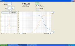
FIR_Lab allows to graphically design complementary phase-linear digital crossovers, FIR-based, in a matter of seconds instead of hours or days.
The sum of the Lowpass and Highpass is the unity transfer function, in amplitude and in phase. As consequence, the acoustic reconstruction will be perfect.
There is no phase shift between the woofer and the tweeter, across all frequencies. As consequence the main radiation lobe should remain stable over the full audio frequency bandwidth, exhibiting no angular shift when varying the frequency.
1 - Basically, the crossover frequency gets defined by a parametric Sinc function (Sinus cardinal) tending to a brickwall filter when the FIR length gets considerable.
2 - The FIR length has a direct influence on the Lowpass and Highpass selectivity, transition band width, and slope. Basically, shortening the FIR length decreases the selectivity, increases the transition band width, and reduces the slope.
3 - Preshoot and ringing can be reduced using a parametric Gauss function applied on top of the Sinc function.
4 - For increasing the smoothness, a triangular window can be applied, as final touch.
The resulting FIR coefficients are written into a c:\FIR_Lab.txt file.
See attached files.
Attachments
Last edited:
It is very easy to implement digital filters with amazing characteristics, but beyond a certain point it just becomes "fun with numbers".
Thanks for those responses gberchin. Merely by formulating the questions I think I was partially answering them for myself in a way, as well.
I'm still not sure I've established the answer to the main question at the top of this thread i.e. exactly why crossover steepness is important. Shallower crossovers allow more contamination of a driver's signal with 'unsuitable' frequencies, while steeper crossovers suffer from filtering artefacts (whose significance is debatable, given the acoustic cancellation of those artefacts). There's also the issue of 'lobing' and 'combing' due to both drivers passing the same signals simultaneously with the shallower crossovers.
Intuitively, it feels as though the weakness of the shallower crossover filtering might become more important at higher volumes, and might depend on signal content. Could there be any mileage in varying crossover filtering dynamically in response to signal content? And of course, with a digital setup, the filtering can be set up in advance of the signal.
Last edited:
That sums it up rather nicely. I would add only power and phase considerations.I'm still not sure I've established the answer to the main question at the top of this thread i.e. exactly why crossover steepness is important. Shallower crossovers allow more contamination of a driver's signal with 'unsuitable' frequencies, while steeper crossovers suffer from filtering artefacts (whose significance is debatable, given the acoustic cancellation of those artefacts). There's also the issue of 'lobing' and 'combing' due to both drivers passing the same signals simultaneously with the shallower crossovers.
It's been done, at least at a primitive level -- the EV DeltaMax system comes to mind.Could there be any mileage in varying crossover filtering dynamically in response to signal content? And of course, with a digital setup, the filtering can be set up in advance of the signal.
It's been done, at least at a primitive level -- the EV DeltaMax system comes to mind.
You wouldn't have a link to that would you, or a good search term? They have a feature called 'FIR-drive' but I can't find any mention of dynamic crossover filtering.
In my post above I was thinking along the lines of analysing the upcoming audio for amplitude, transients against quiet backgrounds, or heavy bass content, and switching (blending) between Gaussian and higher order filters where necessary, for example.
Or, if dynamically changing the filtering is a psychological no-no, with a PC-based system in a home audio situation you could analyse an entire track and set up an optimum crossover configuration for the whole track - if the user adjusts the volume part way through you might have to re-calculate (but if it takes more than a moment, you could do that in the background perhaps without disturbing the playback unless absolutely necessary. As soon as the volume is increased you could switch to a 'failsafe' crossover mode, re-calculate then switch over to the new configuration from then on. That sort of thing.)
No; I'm afraid it's been over fifteen years since I worked with that. I just recall that the system modified compressor, limiter, and (I think) crossover parameters based upon power levels and driver heating. I could be mistaken.You wouldn't have a link to that would you, or a good search term? They have a feature called 'FIR-drive' but I can't find any mention of dynamic crossover filtering.
But why? Don't forget that what you describe amounts to a form of modulation, which is almost guaranteed to corrupt the sound. DeltaMax did it under extreme conditions -- in sound reinforcement situations to avoid blowing things up. In the home you're not encountering anywhere near those power levels or SPL values.Or, if dynamically changing the filtering is a psychological no-no, with a PC-based system in a home audio situation you could analyse an entire track and set up an optimum crossover configuration for the whole track
Or, if dynamically changing the filtering is a psychological no-no, with a PC-based system in a home audio situation you could analyse an entire track and set up an optimum crossover configuration for the whole track
But why? Don't forget that what you describe amounts to a form of modulation, which is almost guaranteed to corrupt the sound. DeltaMax did it under extreme conditions -- in sound reinforcement situations to avoid blowing things up. In the home you're not encountering anywhere near those power levels or SPL values.
I don't think I'm talking about things blowing up, but selecting the optimum crossover for a particular signal/volume level. The whole controversy over crossover design seems to be that shallow crossovers are considered desirable in many ways, but fall down in certain circumstances. e.g.
(from DEQX sales blurb)...single-pole crossovers... provide almost no protection at all for tweeters and midrange drivers from unfortunate driver excursions that causes break-up distortion, compression and reduced resolution.
Steep crossovers would always be better, except for their side-effects, particularly audible on certain sounds e.g. sudden transients against a quiet background showing up 'pre-ripple'. Just saying that with a PC-based system, you needn't compromise, or adjust the settings manually, but make an assessment of the audio that's coming up 'scientifically' and set the crossover up in advance. You can do it dynamically (but with a time constant of several seconds if you think it might avoid some sort of audible pumping or whatever) or simply select a fixed crossover setting for the whole track - the sort of thing you might do yourself manually if you were keen.
From my brief experiments, with my ears and speakers, switching rapidly between 2nd order non-Gaussian and 256th order at a fixed volume on real music is not offensive, so I would bet that you could get away with more subtle dynamic changes inaudibly, yet avoid the worst problems of the wrong crossover for the wrong material and signal level.
(If it's not all that important, let's just stick with the ubiquitous 4th order Linkwitz Riley-style filter and go home, but if it really would be nice to use the pure Gaussian where possible, the PC would allow you to do it without running into problems on 'extreme' signal content).
That seems to be the preferred solution. Personally, I don't care for the sound of L-R crossovers, but that's just my opinion.(If it's not all that important, let's just stick with the ubiquitous 4th order Linkwitz Riley-style filter and go home,
Well, I'm a big fan of keeping things simple. If your tweeter can't live with a 2nd-order highpass characteristic with 'typical' signal content, then my suggestion is that you either cross it over an octave higher or find a better tweeter. If your tweeter cannot live with a 2nd-order highpass charactistic with 'extreme' signal content, then my suggestion is that you implement a system-protection limiter.but if it really would be nice to use the pure Gaussian where possible, the PC would allow you to do it without running into problems on 'extreme' signal content).
Don't forget that what you describe amounts to a form of modulation, which is almost guaranteed to corrupt the sound.
Yes, but am I right in thinking that the separate modulations of the signals to the drivers would cancel out assuming we are using complementary filters? (with the caveat that they may not cancel out perfectly acoustically).
If I understand the problems of the shallower crossover correctly, is it the case that if a driver is presented with a signal component it cannot reproduce properly, then the complementarity (yes, it's a real word!) of our filters/drivers system falls down? Doesn't that constitute a real modulation of the signal, anyway?
My experience with a real system is that, as yet, I can't settle on your pure Gaussian or alternatively a steep crossover without listening for audible artefacts, and the intermediate settings seem like a bit of a waste of the system's capability. If, instead we subtly maintained the steepness (and cutoff frequency) of the crossover to ensure that no signal reached the drivers that could not be reproduced properly, the listener would get the reassurance of the simplicity of the pure Gaussian most of the time, with only an occasional drift into a steeper crossover when essential - maybe not at all in many musical tracks.
I can just imagine the user interface... the glossy sales brochure... the graphs, the block diagrams...
It depends upon the implementation. What if the midrange filter is being modified by both the woofer filter and the tweeter filter simultaneously? Will everything still remain complimentary?Yes, but am I right in thinking that the separate modulations of the signals to the drivers would cancel out assuming we are using complementary filters? (with the caveat that they may not cancel out perfectly acoustically).
Of a sort, I guess -- intermodulation due to a nonlinearity.If I understand the problems of the shallower crossover correctly, is it the case that if a driver is presented with a signal component it cannot reproduce properly, then the complementarity (yes, it's a real word!) of our filters/drivers system falls down? Doesn't that constitute a real modulation of the signal, anyway?
And the same end result can be accomplished with much greater simplicity by means of the suggestions I put forth in my previous message -- proper system design, taking into account driver capabilities, combined with system protection for severe situations.If, instead we subtly maintained the steepness (and cutoff frequency) of the crossover to ensure that no signal reached the drivers that could not be reproduced properly, the listener would get the reassurance of the simplicity of the pure Gaussian most of the time, with only an occasional drift into a steeper crossover when essential - maybe not at all in many musical tracks.
I don't think that I am going to dissuade you from your point of view, nor will you dissuade me from mine. Such is the nature of this hobby.
@gberchin
Just out of interest, do you know if anyone has ever actually used the Gaussian filter for crossovers as described in your paper? There doesn't seem to be any mention of it out there on the WWW except in passing.
If I were a digital crossover manufacturer I'd include it like a shot, and point the potential customer towards your paper on the subject.
Not to my knowledge. Electro Voice applied for a patent, but I do not know whether they pursued it to issuance (I haven't been affiliated with EV since 2000). I have implemented them for my own personal use, but have never pursued any commercial sales.@gberchin
Just out of interest, do you know if anyone has ever actually used the Gaussian filter for crossovers as described in your paper?
When I first ran my PC-based crossover, I was absolutely thrilled by the sound of it, even though I was using a naive 'linear' crossover slope: the frequency response of the low pass is flat* until, say 3 kHz, then slopes linearly to zero* over, say a couple of kHz. The high pass does the exact opposite.
Since starting this thread, I've learned how to do the filtering properly, using proper dB/octave slopes simulating Butterworth etc. I've also experimented with the theoretically optimum (albeit shallow) crossover filter: the pure Gaussian.
Unfortunately, the system has no longer sounded as thrilling in recent days; a bit 'muddled' perhaps. Now, I'm the arch-sceptic when it comes to trusting my own hearing with subtle changes - experimenter bias and all that - but... I decided to go back to the original linear crossover slope. And to me, it really does sound better.
In the last few posts we've been talking about shallow crossovers causing intermodulation when signal components reach the drivers that they're incapable of reproducing properly. Whereas, steep crossovers ring and overshoot, so we're relying on acoustic cancellation to neutralise the effect.
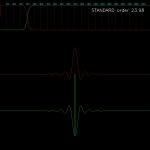
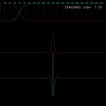
If I look on a linear/linear scale at the frequency response of, say, a 4th order 'standard' filter on a crossover frequency of 4 kHz, I can see that the tweeter is still going to be getting some 'visible' signal at just over 1 kHz, and the woofer will be getting something at up to 14 kHz. Surely this must cause some audible degradation. The situation with the 8th order is a little better, but not great. (If you insist I can go away and come back with some properly measured figures!)
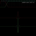
If I switch to the linear crossover, I can set it at, say, a precise 2 kHz width, and be sure that the amplitude to each driver will be zero* outside of this range. The impulse response shows minuscule ringing for a long time on either side of the centre - far longer than any 'standard' filter, but the central ringing and overshoot looks fairly tame.
To get something approaching the same level of attenuation at the extreme frequencies using a 'standard' filter, I reckon I would need to use 24th order. The central slope would be steeper than that of the linear filter, (but unless it's lobing we're concerned with this is the region where we're confident in our drivers' abilities), and would, in fact, give rise to much higher overshoot and ringing close to the centre of the impulse response.
Does this suggest that we want our crossover filter to be steepest at both extremities of the crossover region where we really want to kill the 'contamination' for each driver while maintaining the complementarity** of the filters, and then we can relax a little in the middle where we're confident our drivers are capable of behaving properly?
Just wondering whether my linear crossover does, in fact, have the advantage of doing something not too far off this..? I could imagine just rounding off the corners a bit, so that the attenuation when very close to zero was more 'asymptotic' or something like that...
I enclose a few screenshots to illustrate what I'm on about.
* It's not perfect, because that would require an infinitely long FIR, probably, but I'm using a pretty large FFT, and even after windowing it's very close. The enclosed images show the frequency response after windowing the impulse response.
** It's a real word!
Since starting this thread, I've learned how to do the filtering properly, using proper dB/octave slopes simulating Butterworth etc. I've also experimented with the theoretically optimum (albeit shallow) crossover filter: the pure Gaussian.
Unfortunately, the system has no longer sounded as thrilling in recent days; a bit 'muddled' perhaps. Now, I'm the arch-sceptic when it comes to trusting my own hearing with subtle changes - experimenter bias and all that - but... I decided to go back to the original linear crossover slope. And to me, it really does sound better.
In the last few posts we've been talking about shallow crossovers causing intermodulation when signal components reach the drivers that they're incapable of reproducing properly. Whereas, steep crossovers ring and overshoot, so we're relying on acoustic cancellation to neutralise the effect.
If I look on a linear/linear scale at the frequency response of, say, a 4th order 'standard' filter on a crossover frequency of 4 kHz, I can see that the tweeter is still going to be getting some 'visible' signal at just over 1 kHz, and the woofer will be getting something at up to 14 kHz. Surely this must cause some audible degradation. The situation with the 8th order is a little better, but not great. (If you insist I can go away and come back with some properly measured figures!)
If I switch to the linear crossover, I can set it at, say, a precise 2 kHz width, and be sure that the amplitude to each driver will be zero* outside of this range. The impulse response shows minuscule ringing for a long time on either side of the centre - far longer than any 'standard' filter, but the central ringing and overshoot looks fairly tame.
To get something approaching the same level of attenuation at the extreme frequencies using a 'standard' filter, I reckon I would need to use 24th order. The central slope would be steeper than that of the linear filter, (but unless it's lobing we're concerned with this is the region where we're confident in our drivers' abilities), and would, in fact, give rise to much higher overshoot and ringing close to the centre of the impulse response.
Does this suggest that we want our crossover filter to be steepest at both extremities of the crossover region where we really want to kill the 'contamination' for each driver while maintaining the complementarity** of the filters, and then we can relax a little in the middle where we're confident our drivers are capable of behaving properly?
Just wondering whether my linear crossover does, in fact, have the advantage of doing something not too far off this..? I could imagine just rounding off the corners a bit, so that the attenuation when very close to zero was more 'asymptotic' or something like that...
I enclose a few screenshots to illustrate what I'm on about.
* It's not perfect, because that would require an infinitely long FIR, probably, but I'm using a pretty large FFT, and even after windowing it's very close. The enclosed images show the frequency response after windowing the impulse response.
** It's a real word!
Attachments
Last edited:
CopperTop, can you post those frequency response plots with a dB vertical scale? And perhaps on a log horizontal scale?
Also, when you refer to your "standard" filters, exactly how are these created?
I haven't quite got round to plotting log axes yet! I'll work on it.
The 'standard' filter is based solely on the formula given in post #71 - I'm not claiming to be an expert on standard filters, so I'm relying on the author's words:
This expression yields an amplitude response with an nth order roll off and a response with magnitude 20 Log(Q) at f = 1.0. For n equal to 2 the amplitude given be Eq(1) is consistent with that of any standard 2nd order filter, Butterworth, Bessel or Linkwitz/Riley, for example. For n greater than 2 the response is only consistent with symmetric higher order filters. These include Butterworth filters (n even or odd, Q = 0.707) and Linkwitz/Riley filter (n even, Q = 0.5), but not higher order Bessel filters
I'm using Q = 0.5.
- Status
- This old topic is closed. If you want to reopen this topic, contact a moderator using the "Report Post" button.
- Home
- Source & Line
- PC Based
- The importance of crossover steepness