hello coris you can bypass the U35 component that has melted '.
I do not know what to do is impossible to desolder and resolder know what you can do?
I have built a linear power supply for 12V 5VE for the molex on the first try the card game and he played it perfectly, then I do not know what happened but as soon as I hung up the aliementazione we saw the smoke and I saw that it was cooked this dc-dc converter.
Thanks.
Michael.
Hi ciccio1112
Sorry to hear about melting and smoke...
There is not easy to desolder components on this card without destroy the traces... This is a fact I may say.
One may have quite good soldering tools to succeed in this task. When you work on very fine traces and enough small components, then you may use a very low power and fine soldering iron. In opposite, when you should solder/desolder components which are in contact with big ground planes, then you may use quite high power soldering iron, and doing quick the operation. I know there may not be enough these advices, but one may destroy something in the beginning to get experience... I did actually like this...
If you see that it may be difficult to desolder, then is better to cut and/or broke the legs of the components, to remove it from the board. Specially the caps it may be removed so, by bending it repeatedly back and forth until the legs are broken. You can solder then on the rest of the legs what you need...
When about a melted U35, I`m not very sure if the card will function without it... It seems to me that it is a chip which control the generating of +12v on the board. But this chip it may be also controlled by another circuits, and give informations to the software about the status of the 12v rail on the card... But anyway, if you will cut the output leg of 7812, or remove the diode before this regulator (right beside U35), then you will isolate the +12v rail from get in to the board circuits.
If one may want to power the board with an external PSU for analogue stages of the board, then this external PSU may not be connected to Molex connector (instead of computer rails). Insert your power as advised in the previous posts here in the thread, The Molex connector it have to be connected as normal to the board to simulate normal functioning of the involved circuits. The +/-12v rails on the board it have to be in function too, but only prevent these rails to feed the board circuits, as indicated many times here in the thread. These PWM PSUs have to function further, because are both controlled and supervised by the processor and the driver software. These it have to work and oscillate as nothing it happen with the board. Else errors occur.
The new inserted power rails (+/-12-15v) in to the board it have to be controlled (on the lower AC tensions of the PSUs, but not on the 220vAc input) by relays and synchronized with the ON/OFF sequences of the computer. The ground of the external PSU it have to be always connected to the board ground plane.
I have to repeat that one may not proceed to such mods as described here, if one do not have enough knowledge about electricity, physics and electronics, and quite professional tools to work with...
Last edited:
I noticed you're using the Ti evaluation PSU board...nice, low cost solution! You just add dual transformers to feed it under 36V?
Can it be easily modified to supply 18-20V output instead of 15V?
Sent from my iPhone...
I intended to use dual transformers. One for +/-15v rails, and another one it were meant to make +5/+3,3v for the DAC. For the moment I will use only one toroid for +/-15v rails, and feed the DAc from the board/computer. If all will be all right, then I may try the power the DAC entirely from my PSUs (put the second transformer in place).
In fact, on my +/-15v rails I can have more than 20v, (are adjustable) to have at least max +/-18v regulated for the final opamp.
Hmmm...using a LM317(?) for adjustability?
Every time I think I have a grasp on this project, I go one step forward and two steps backwards! Lol
You know I'm using my super-over complicated regulator board with my project. I plan in using a simple, regulated (maybe) center tap transformer PSU for -+20 V output to power it.
Now just to be sure, I just have to trim/ desoldered leg 3 of the 7812 and solder my regulated 15+V there and desolder diode above U34 to isolate - V and feed my -15V to leg 3 of U34 and ground everything to the pair of serial connected caps at the ground plane...?
With the molex still attached for powering everything else except the analog stage.
My low jitter clock has discrete PSU...I'll have to double check if I can feed it the 20V from the transformer...ideally this would be slightly better than feeding it from my -+15V regulator board.
Sent from my iPhone...
As for the space "inside" my PC for all of this....room isn't really an issue. Lol
I plan on mounting the regulator board using a custom made "null" PCI slot to mount it near the top side of the card, and the same with the PSU but mounted in the AGP slot near the bottom side of the card...
Or both on one side of the STX.
Sent from my iPhone...
An externally hosted image should be here but it was not working when we last tested it.
I plan on mounting the regulator board using a custom made "null" PCI slot to mount it near the top side of the card, and the same with the PSU but mounted in the AGP slot near the bottom side of the card...
Or both on one side of the STX.
Sent from my iPhone...
Hmmm...using a LM317(?) for adjustability?
Every time I think I have a grasp on this project, I go one step forward and two steps backwards! Lol
You know I'm using my super-over complicated regulator board with my project. I plan in using a simple, regulated (maybe) center tap transformer PSU for -+20 V output to power it.
Now just to be sure, I just have to trim/ desoldered leg 3 of the 7812 and solder my regulated 15+V there and desolder diode above U34 to isolate - V and feed my -15V to leg 3 of U34 and ground everything to the pair of serial connected caps at the ground plane...?
With the molex still attached for powering everything else except the analog stage.
My low jitter clock has discrete PSU...I'll have to double check if I can feed it the 20V from the transformer...ideally this would be slightly better than feeding it from my -+15V regulator board.
Sent from my iPhone...
I can see now in your picture a nice audio computer project. Yes, there is a plenty of space there...
Cutting the output leg of the 7812 you isolate the internal positive PSU for the rest of the board. This PSU will continue to work well, but will not deliver power to the board. You can insert your positive power rail on that tab of 7812 or on another points, as you can see on my last pictures. There is a clue to use the filtering cells already existing on board.
Above u34 there is a ferrite bead to be removed to isolate the internal negative PSU, but not a diode... You can see in my picture that under that component there is pictured on the board as a coil... There is a little bit difficult to remove that ferrite bead. I will suggest to use a soldering iron which is wide enough on its top, to cover both ends of the component. Then put on the soldering iron quite much soldering tin to get wet/hot both ends of the component in the same time. Then it will desolder it quick and well, without damaging the tabs.
The same, you can insert your negative power on that point/tab of the removed ferrite bead, on the side with the filtering caps. On other side there is the -12v from PWM PSU. You can measure actually in between to have good control over the operations... GND is to be connected as you said in between the ones of the serial coupled caps (there are few such mounted as filtering cells).
After removing the components and isolate the internal +/- power to feed the board circuits, with Molex connector in its place, you my start up the computer, the relays on sound card will click as normal, no errors in the driver, but you will not have sound at all if you will play something... After you will connect your external PSU, to the board, you will have the sound too... Maybe better...
")
Heaving a better power system in place, you may start experiment with different opamps, filtering caps and so on... As I understood, you have already an improved clock system.
So, good luck!
Last edited:
Ahhh...okay, I'm following you. I can see the little silk screened coil image now. That clears up a lot for me, thanks.
You removed both - and + ferrite beads I see. Connecting my PSU to these points still employes the filtering caps then?
And thanks for the compliment on my PC...
You have two different insertion points for power...the one above and this earlier picture...
Which do you recommend?
Thanks
Sent from my iPhone...
You removed both - and + ferrite beads I see. Connecting my PSU to these points still employes the filtering caps then?
And thanks for the compliment on my PC...
You have two different insertion points for power...the one above and this earlier picture...
An externally hosted image should be here but it was not working when we last tested it.
Which do you recommend?
Thanks
Sent from my iPhone...
If you want to use the on board filtering cells, you may use the insertion as in the picture above. One may remark that the filtering cells it were designed to filter the noises coming from the PWM PSUs, but have minimal filtering properties when about a serial lower noise external PSU, like this case.
If you want to have short connections, when external PSU is placed on the back of the board, then it may be used the solution presented in post 460...
So many possibilities...
If you want to have short connections, when external PSU is placed on the back of the board, then it may be used the solution presented in post 460...
So many possibilities...
Hello Coris know exactly what the DC component DC inverter?
Can this be?
Converter (Integrated Switch) - Inverting Converter - TPS63700 - TI.com
I would like to rework the old damaged, but I need to know what it is exactly.
Thank you.
Can this be?
Converter (Integrated Switch) - Inverting Converter - TPS63700 - TI.com
I would like to rework the old damaged, but I need to know what it is exactly.
Thank you.
Last edited:
Hey Coris...
I'm looking at a Hammond toroidal trans...
182J18, 18V center tapped and 2.8A.
The data sheet wiring had me a bit miffed however...
For +18 and -18, I just tap into the secondaries separately...? They just show series and parallel (both, I think for 36V output?)
Thanks
Sent from my iPhone...
I'm looking at a Hammond toroidal trans...
182J18, 18V center tapped and 2.8A.
The data sheet wiring had me a bit miffed however...
An externally hosted image should be here but it was not working when we last tested it.
For +18 and -18, I just tap into the secondaries separately...? They just show series and parallel (both, I think for 36V output?)
Thanks
Sent from my iPhone...
Hey Coris...
I'm looking at a Hammond toroidal trans...
182J18, 18V center tapped and 2.8A.
Actually...it might NOT be center tapped, but has dual output...?
The data sheet wiring had me a bit miffed however...
An externally hosted image should be here but it was not working when we last tested it.
For +18 and -18, I just tap into the secondaries separately...? They just show series and parallel (both, I think for 36V output?)
Thanks
Sent from my iPhone...
Sent from my iPhone...
Hello Coris know exactly what the DC component DC inverter?
Can this be?
Converter (Integrated Switch) - Inverting Converter - TPS63700 - TI.com
I would like to rework the old damaged, but I need to know what it is exactly.
Thank you.
I can not know exactly the chip name. Anyway it may be a positive output DC converter, as its output goes further to the 12v positive rail...
Try to disconnect the +/- PSUs by removing the respective ferrite beads, and with that melted chip on board, if is recognized by the driver, no errors, and the relays clicking as normal on start up, you may not bother so much about that chip. Just feed the board from a external double PSU and should work...
If not the case, then it may be difficult to fix it...
Last edited:
Sent from my iPhone...
I think you may not need a 2,8A output transformer for the task... 15v AC at 0,3 - 0,5A it may be more than enough... A toroid with two identical coils is very usual and quite good for this job.
I can not know exactly the chip name. Anyway it may be a positive output DC converter, as its output goes further to the 12v positive rail...
Try to disconnect the +/- PSUs by removing the respective ferrite beads, and with that melted chip on board, if is recognized by the driver, no errors, and the relays clicking as normal on start up, you may not bother so much about that chip.
Thanks coris.
The ferrite bead say the two after the molex? I thought that was used for the u35 -12 V for the opamp. Then the-12V is generated by what?
So the DC DC converter that I said I'm not okay?
And 'this http://www.ti.com/lit/ds/symlink/tps61086.pdf
You can measure the output voltage of this u35?
I think you may not need a 2,8A output transformer for the task... 15v AC at 0,3 - 0,5A it may be more than enough... A toroid with two identical coils is very usual and quite good for this job.
I'm thinking the regulator board I'm using would be somewhat power hungry itself
I'll aim for 1A to 1.5A to be safe.
Sent from my iPhone...
hi coris...
gonna hook up my reference clock today. Could you translate this pic for me please...?
http://www.nexthardware.com/forum/a...-stx-parte-seconda-lupgrade-estremo-fig.2.jpg
im assumimg once the old crystal is desoldered, 1 is clock signal, 3 is signal ground?
my reference clock has its own power regulator and smoothing...is there a pin on the STX that will allow direct feed of the signal, bypassing the onboard smoothing/resistors on the STX? was not able to find the info on this post
Hi Wungun
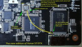
You have here the pics with these mods (old and new ST/STX).
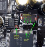
I assume your clock circuit it may need 5v power. If so, you may use the output pin of the on-board 7805 regulator. If your clock is to be powered from 3,3v, then you may use 3,3v rail on card. I think you will find a picture where that rail is shown, in my earlier posts.
The 3,3v point shown in this picture here (new Xonar edition) it may be used only for standard oscillators, as this rail come from a dedicated regulator (not so powerful).
Very (extremely) short connections is a must in the oscillators case... Using quite big components, or circuits on own PCB (like a "reference clock") it may not be very fortunate, because it may require long connection wires ... If so, one may use some sort of coaxial to transport the clock frequency to the desired point (but I will not recommend such assembly).
You have here the pics with these mods (old and new ST/STX).
I assume your clock circuit it may need 5v power. If so, you may use the output pin of the on-board 7805 regulator. If your clock is to be powered from 3,3v, then you may use 3,3v rail on card. I think you will find a picture where that rail is shown, in my earlier posts.
The 3,3v point shown in this picture here (new Xonar edition) it may be used only for standard oscillators, as this rail come from a dedicated regulator (not so powerful).
Very (extremely) short connections is a must in the oscillators case... Using quite big components, or circuits on own PCB (like a "reference clock") it may not be very fortunate, because it may require long connection wires ... If so, one may use some sort of coaxial to transport the clock frequency to the desired point (but I will not recommend such assembly).
Attachments
Last edited:
- Home
- Source & Line
- PC Based
- Xonar ST/STX mods...