Nelson Pass said:Who do you think I am, JC ?
For the 2-0h-0h-8 international funniest contest, L'Amerique : diezzze points.
Wouldn't it be smarter if you guys find out for yourself ?
Bypass the coupling lytics with foil caps, replace them entirely by 220uF worth of cheap KP motor start capacitors, and listen to your own ears.
(overhere a NOS 30uF KP cap costs around $3/pc, cheaper than 4-pole Jensen's)
Today I finally received my Kendeil caps for the PSU. Instead of eight, they gave me ten 15.000uF 35V caps; the question is: is it reasonable to use all of them, putting an extra cap together with the other ones in each rail?
And if you say yes, where is it better? Before the four resistors or after them?
Thank you!
Giacomo
And if you say yes, where is it better? Before the four resistors or after them?
Thank you!
Giacomo
 )
)Nelson Pass said:Who do you think I am, John Curl?
10 uF
...obviously I meant C1-C4 in your schematic.
THX a lot..that helps...I will now go and buy some of the more expensive ones..or even use some old KP paper in Oil...this value gives a lot of freedom to play with parts...It would have made no sense if I needed 100uF or more
This John Curl-Joke I did not understand, I think he has been the devleoper of the Parasound Products if I recall right, but for what characteristic does he stand for (...to get your joke) ?
RC 1-Oh-1 : C3+C4 are merely there to reduce the powersupply ripple and bump up the S/N.
RC 1-Oh-2 : seen resistors R3+R4 in front of C1+C2 ?
(Mr Curl does gourmand cuisine with ByBees as truffles and foil caps as turkish delight.
Not much good if you'd like to serve an honest stew with day fresh seasonal pickings, flushed down with 2 pints of grape juice)
RC 1-Oh-2 : seen resistors R3+R4 in front of C1+C2 ?
(Mr Curl does gourmand cuisine with ByBees as truffles and foil caps as turkish delight.
Not much good if you'd like to serve an honest stew with day fresh seasonal pickings, flushed down with 2 pints of grape juice)
Thank you Jacco. You're right, it's just stereo, maybe I'll upgrade to dual-mono in the future (there are some money issues right now here).
Last question, and I think the amplifier is ready (at least the electronic part of it, cabinet is under construction): I only found these two types of thermistors, apparently similar to the original CL60:
- R(25): 10 ohm; I: 3A; B(25/100): 2900K
- R(25): 5 ohm; I: 5A; B(25/100): 2900K
I'm on 220VAC. Which one do you think I should use?
If I could avoid them, I would be glad to do it, but I don't know about the effect of that 150.000 uF capacitance on startup.
Suggestions are welcome.
Giacomo
220/5= 44 amps, peaking to 62A, would you call that a slow start ?
220VAC x 3A =660VA, more than 4 times the continuous power draw of two F4 channels.
In reality, your mains voltage will be 230-235VAC, allowing the power draw through the 3A thermistor to max out at 700 Watts.
NTC thermistors are cool devices, why avoid them ?
A big advantage of splitting your pretty Kendeil caps between the two channels is halving the current draw.
The RC constant remains the same if you half the capacitor value and double the CRC resistor number.
Half the current and twice the resistor value makes the voltage drop across the CRC identical, but the resistor dissipation will be halved as power= current squared times ohm.
Does require extra windings or a second transformer, plus the most important => pecunia, aka clams.
(the coupling caps are charged/decharged through R3/R4, so they can't have too large a value. They're loaded by mA, in contrast with a lytic at a SE output stage or a single rail OS they do not need to be large to transfer enough power at low frequencies. On the other side of the amp, C1+C2 are part of high pass RC filters. All the K-range resistor values after C1/C2 hardly have an influence, it should be easy enough to calculate the RC high pass corner freq. for lower value coupling caps)
jacco vermeulen said:
(the coupling caps are charged/decharged through R3/R4, so they can't have too large a value. They're loaded by mA, in contrast with a lytic at a SE output stage or a single rail OS they do not need to be large to transfer enough power at low frequencies. On the other side of the amp, C1+C2 are part of high pass RC filters. All the K-range resistor values after C1/C2 hardly have an influence, it should be easy enough to calculate the RC high pass corner freq. for lower value coupling caps)
I have right now neither my formular book with me nor my simulator...will look into it at the weekend, but this makes a lot of sense, thanks for explanation...
Could it be that you mixed the nueration up: C1 and C2 are charged through R3/4 (in the actual schematic online at firstwatt?), not C3/C4.
so, if we really have only a few mA, and as we understand C1 and C2 as coupling caps: I guess the fastest, high-quality cap (like Mundrorf supreme) with a normal size like 1uF would make here a difference ? Your thoughts ?
If any one has his formular book infront of him, would be great if you could do the maths for the RC-filter...I am not the master in circuit design to be honest (I appreciate Nelson's guidance towards 10uf, nevertheless a 10uf Mundof Supreme is still a monster of a Cap, so if we could go down to 1uF we have a new playground whee all high-end-caps could be used.
You're not getting the message.
f= 1/[(2*Pi*R*C]
Take the C3 + C4 ripple filter, a low pass with either R5 or R22+Psomething :
f= 1 /[ 2*3.14159265*3320 Ohm*220 uF)= ~0.2Hz, low pass filters are 10dB down for every decade.
Same same for high pass filters: a 1uF foil coupling cap means losing an estimated 23dB at 20Hz, compared to a 220uF electrolytic.
jacco vermeulen said:220/5= 44 amps, peaking to 62A, would you call that a slow start ?
220VAC x 3A =660VA, more than 4 times the continuous power draw of two F4 channels.
In reality, your mains voltage will be 230-235VAC, allowing the power draw through the 3A thermistor to max out at 700 Watts.
NTC thermistors are cool devices, why avoid them ?
ROTFL (the soft start thing)
So, are you suggesting me to use the first one (3A)?
I don't have two primary windings as shown in Mr. Pass' schematics, so I guess I can just put it in series between the AC switch and my primary winding...
I see there's also a thermistor in series towards earth, can I use the 10 ohm / 3 A thermistor there as well?
Thank you so much for the help
")
Giacomo
Remember : general mains voltage in the US is half of 230VAC.
In the EC area it makes more sense to pick a 20 Ohm than a 5 Ohm thermistor, if you choose other than a CL60 : 115VAC divided by the 10 Ohm of a CL60 = 11.5A
I'm saying 25W/8 is weeny sausage power, and 3A is a lot of current on the primary side of a transformer.
(prego, but the main reason i'm doing it is to provoce NP to slap me with some books again)
jacco vermeulen said:I'm saying 25W/8 is weeny sausage power, and 3A is a lot of current on the primary side of a transformer.
[/B]
I never thought about it... I only supposed that the thermistor was there to avoid lights to turn off in my house while firing the amp up.
Now that you point it out, I'm confused... Do you think my 400VA transformer would be damaged by the inrush current, with the 10ohm/3A thermistor?
I see that distrelec has got 22 ohm ones as well, but it's 2.5A, still high...
Giacomo
If you visit the Plitron home page, there used to be a toroidal inrush current graph somewhere in the technical section.
Toroid transformer inrush current peaks are gigantic, but they last only in the mS range.
400/220~1.8A.
3A/1.8A= 5/3, means that a 3A thermistor has at least 2/3d spare capacity for a 400VA transformer.
I'd just go for the 10 Ohm and 3A model.
Found a picture of the KP cap i mentioned, i bought a "number" for far less than the $3/pc tag to make a Lyra-like powersupply.
Attachments
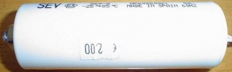
jacco vermeulen said:Found a picture of the KP cap i mentioned, i bought a "number" for far less than the $3/pc tag to make a Lyra-like powersupply. [/B]
 Jacco has too many toys!
 jacco vermeulen said:........
Found a picture of the KP cap i mentioned, i bought a "number" for far less than the $3/pc tag to make a Lyra-like powersupply.
they must be eeeny weeeny in value , counting on fact that you didn't show uF number .......

jacco vermeulen said:Found a picture of the KP cap i mentioned, i bought a "number" for far less than the $3/pc tag to make a Lyra-like powersupply. [/B]
Did you already make this PSU?
Manu
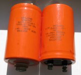
I bought this red cans recently... are they good?
Attachments
Manu said:
Did you already make this PSU?
Manu
I bought this red cans recently... are they good?
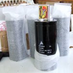
naah ....... they're for sissies

these ones are for grown-ups
Attachments
- Home
- Amplifiers
- Pass Labs
- F4 power amplifier