I thought you figured that out though???
flg, when it comes to my ZV7, I'm flying by the seat of my pants. I don't really know much about gain, though I'm trying to learn. Your posts get to the heart of the matter, and do so in short order.
I just plug things in and see what happens. Both approaches work, and for a newbie, it can be a rather exciting ride.
I like the way you calculate gain by keeping the dc out of the front end. Hopefully, I got that right? Do you just divide 100k by 10k to get a gain of 10? I'd enjoy reading how you arrive at the proper mathematical conclusion.
I could put a cap in series with my 442K feedback resistor to eliminate DC and find another way to set the bias point on the buffer. Seems to me that babowana suggested this a long time ago. This approach could allow greater flexibility.
For the input impedance of my amp, do I use a product-over-sum approach with the 442k and the 147k resistor? If so, does the input impedance have anything to do with gain?
I don't mean to swamp you, just curious about these things? I'm reading 4 hours a day in my $1.42 Malvino book. Man, that guy's wonderful! I'm learning a lot.
I can't wait to read about your experiences with the buffer,
John
")
I do enjoy reading your posts!
I think the gain calc is close enough. If you actually set up the gain to be huge, it will only end up has high as open loop. Which really isn't that high in either of our amps.
I have some things to go do right now... I'll get back to you. I wanted to see your amp Schez(in the ZV7-T thread) before I say much about yours though...
I have some things to go do right now... I'll get back to you. I wanted to see your amp Schez(in the ZV7-T thread) before I say much about yours though...
carpenter said:I'm reading 4 hours a day in my $1.42 Malvino book.
Mine is Fifth Edition
1979 is the year of the second edition. You probably had the 1973, first edition--considering that you graduated the year the second edition came out.
You can find these deals cheap on Amazon.com. Go to the used book section.
Mine is a "staff" book, and is in perfect condition. What a buy...
John
You can find these deals cheap on Amazon.com. Go to the used book section.
Mine is a "staff" book, and is in perfect condition. What a buy...
John
A staff book??? Does that mean it has an enffection
No. I really don't want to see that book ever again I'm waiting for the "Nelson Pass's First Watt of the Audio Power Amp" Or whatever he call's his first book The last book I read regarding our hobby is the Doug Self, Audio Power Amplifier Design Handbook. It is good. But, I'm not sure your ready to dig out that sh** I honestly can;'t suck up all that stuff...I'll help you if you do... It's got alot of good points... He would be a more well known name if it was the end all. But he isn't... Basically we are chasing down Class A stuff and he isn't... I'd really like to see John Curl on this Forum more often... He's probably holding out for the Curl Forum
Anyway, for me and the interest of others, I should get some real THD and stuff numbers from what I have and some tweaks, as N.P. suggests, before I modify it to the dual JFET gain stage

No. I really don't want to see that book ever again
I'm waiting for the "Nelson Pass's First Watt of the Audio Power Amp" Or whatever he call's his first book The last book I read regarding our hobby is the Doug Self, Audio Power Amplifier Design Handbook. It is good. But, I'm not sure your ready to dig out that sh** I honestly can;'t suck up all that stuff...I'll help you if you do... It's got alot of good points... He would be a more well known name if it was the end all. But he isn't... Basically we are chasing down Class A stuff and he isn't... I'd really like to see John Curl on this Forum more often... He's probably holding out for the Curl Forum Anyway, for me and the interest of others, I should get some real THD and stuff numbers from what I have and some tweaks, as N.P. suggests, before I modify it to the dual JFET gain stage
Well, where have we all been??? ZV7-T'ing it? Zen-9'ing it? F4'ing it?
No new responses or experimental results from the "Choke Loads for Zen-Aleph Amps" thread...
No new posts on the "Pathos Amplifiers" thread...
And, I guess I'm the one to try to bring this idea back to life
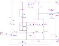
This is where I'm at: I recently recieved a couple Hammond 195T5 Chokes. I tested them in a single and dual JFET gain stage as previously described (1.7A & 3.4A idle current). I can report the curvature of the square wave is gone until down to about 25-30Hz. I guess that's the saturation area although idle current seemed to make very little if any difference... The tilt of the square wave "plateau" is still there somewhat below 100-200Hz??? I think that is the inductance value showing itself. I see a little ringing in the rising edge but that was running open loop. I'm going to aim for a gain of about 8 with 6db of global FB...
I'm currently in the process of collecting some additional components and laying out a PCB to make it nice and tidy. Not sure exactly how to do the chasis yet. Probably going the monoblock route though...
I'll include the latest ideas in a pic
No new responses or experimental results from the "Choke Loads for Zen-Aleph Amps" thread...
No new posts on the "Pathos Amplifiers" thread...
And, I guess I'm the one to try to bring this idea back to life
This is where I'm at: I recently recieved a couple Hammond 195T5 Chokes. I tested them in a single and dual JFET gain stage as previously described (1.7A & 3.4A idle current). I can report the curvature of the square wave is gone until down to about 25-30Hz. I guess that's the saturation area although idle current seemed to make very little if any difference... The tilt of the square wave "plateau" is still there somewhat below 100-200Hz??? I think that is the inductance value showing itself. I see a little ringing in the rising edge but that was running open loop. I'm going to aim for a gain of about 8 with 6db of global FB...
I'm currently in the process of collecting some additional components and laying out a PCB to make it nice and tidy. Not sure exactly how to do the chasis yet. Probably going the monoblock route though...
I'll include the latest ideas in a pic
Attachments
Interesting schematic, Lee. Is the 2SJ a smoother sounding fet than the P3310? I was wondering if it would be of benefit to switch the two; let the 3310 be the current source?
Have you given your idea a listen, or are you going for the pcb first?
Fun stuff to play with, I'm sure.
I'm having a ball with my ZV7-TJBC (jfet; buffered; cascoded). What a fine experience. I've received three pcbs from Express PCB and will construct a final prototype amplifier, soon. At this moment, I'm designing a pcb with ground-plane in a joint effort with Magura; more fun than any human should have... am I a lucky guy, or what?
One last thing; this regards candy stores: Apex Jr. is an excellent place to shop; great products at incredible prices! I just purchased four 200 v/a transformers with steel casings for $15.00 each. They work beautifully in the 20 volt version of my ZV7-TJBC. I also purchased two 1600 v/a transformers for $45.00 each for the larger amplifiers...uhhh, my electric bill went up $30.00 a month...ooops. (If I keep bragging Steve up, I'm going to have to charge an advertising fee...ha)
Keep us posted on your success, Lee. Your enthusiasm is a breath of fresh air.
John
Have you given your idea a listen, or are you going for the pcb first?
Fun stuff to play with, I'm sure.
I'm having a ball with my ZV7-TJBC (jfet; buffered; cascoded). What a fine experience. I've received three pcbs from Express PCB and will construct a final prototype amplifier, soon. At this moment, I'm designing a pcb with ground-plane in a joint effort with Magura; more fun than any human should have... am I a lucky guy, or what?
One last thing; this regards candy stores: Apex Jr. is an excellent place to shop; great products at incredible prices! I just purchased four 200 v/a transformers with steel casings for $15.00 each. They work beautifully in the 20 volt version of my ZV7-TJBC. I also purchased two 1600 v/a transformers for $45.00 each for the larger amplifiers...uhhh, my electric bill went up $30.00 a month...ooops. (If I keep bragging Steve up, I'm going to have to charge an advertising fee...ha
) Keep us posted on your success, Lee. Your enthusiasm is a breath of fresh air.
John
I have a mission:
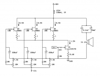
I have previously played with a L loaded R100 Zen, but with my current speakers it has too high distortion at 100-200 hz. So now I want to build a more powerful and better performing amp with a similar sound signature. I also want it to be a current source amp with 100 ohm or higher output impedance.
As I also currently have 6x unused R085s here is my idea. The R085s are unmatched so I have setup individual pots for each.
My questions, however, are:
- Is there some flaw in the design?
- Does the R values look alright? I'm not sure on the 1R source resistors for the R085, should I have lower values or higher or does it look alright? Should I have higher values on the R085 gate stoppers?
Attachments
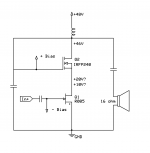
why wasting R085 on cascode duty , when you can use regular IRFP there ?
say that you can use pair of IRFP150 , to cover 1A5 x 45V dissipation
you don't need source resistors there at all , current is defined with LU , while those up are just voltage umbrella
wanna trade some of your R085 for some of my LU ?
say that you can use pair of IRFP150 , to cover 1A5 x 45V dissipation
you don't need source resistors there at all , current is defined with LU , while those up are just voltage umbrella
wanna trade some of your R085 for some of my LU ?
why wasting R085 on cascode duty , when you can use regular IRFP there ?
say that you can use pair of IRFP150 , to cover 1A5 x 45V dissipation
you don't need source resistors there at all , current is defined with LU , while those up are just voltage umbrella
wanna trade some of your R085 for some of my LU ?
Won't they perform better than say IRFP240s? Or is the distortion caused by the upper parts is overshadowed by that of the lower part?
And in that case I guess it would be a better idea to try a R085 in the lower position and se how it compares to to the LU1014D?
Sadly I already have 10x LU1014Ds to play with. If you have a surplus of R100s or R125s lying around though I might take you up on that as I have previously found them less fiddly to sound good but I don't have as many of them.
if biasing of cascodes is done properly , they're pretty much invisible , while doing work intended
LU cascoded , or SS , as active part - you must judge what's better to your pleasuring apparatus
sorry , don't have SS surplus ; several pairs for my own playground , and that would be exactly enough

LU cascoded , or SS , as active part - you must judge what's better to your pleasuring apparatus
sorry , don't have SS surplus ; several pairs for my own playground , and that would be exactly enough
Or is it like this?
The think I don't yet understand though is how they play with each other. If we start simple and ignore modulated cascodes, if the top IRFP part now is just an umbrella does that mean that it does not contribute to the output signal and is equivalent to wasting the watts it dissapates.
Or do the two devices now act kind of like a single device, but where only the lower device takes care of the voltage gain and it is buffered from variances in Vds thus performing better? But both contribute to the output signal like if they were a single device so I don't waste say half of my output power.
And lastly, is there a general guideline for about how much % of my voltage I should put over each device?
Thanks again for being so helpful Zen!
Not the first time you help me when I ask dumb questions
Attachments
cascoded part and cascode - you can look at them as one part , so no wasting of voltage
for proper cascoding (setting) of LU - best literature is Papa's article about Zv9 , but you already know that
regarding cascodes generally ..... Papa's articles page , then http://www.firstwatt.com/pdf/art_cas_amp.pdf
start with that
for proper cascoding (setting) of LU - best literature is Papa's article about Zv9 , but you already know that
regarding cascodes generally ..... Papa's articles page , then http://www.firstwatt.com/pdf/art_cas_amp.pdf
start with that
- Status
- This old topic is closed. If you want to reopen this topic, contact a moderator using the "Report Post" button.
- Home
- Amplifiers
- Pass Labs
- L Loaded ZV9 Help???