Ian Macmillan said:Presumably this must involve additional complexity (hence the SMD solution) but so far nobody has even speculated as to what this might be. Any ideas?
Imagine a twofold attenuation, one row for steps of 10dB the
other for 1 dB steps. This leads to say 15 - 20 switches, 15 - 20
shunt resistors, 15 - 20 BJTs to drive the switches and convert
base voltage from TTL level to +- 5V, lots of caps and resistors
surrounding all those BJTs - all in all about 5 - 7 parts per step.
Now you have about 75 - 150 parts just for one channel.
I would consider this a high enough part count for going modular
and SMT.
Uli

Nelson Pass said:Not much of a challenge since anyone who wants to can take
one apart. Of course you might have to buy one to do
it. Also, it's all SMT so get yourself a microscope.

I do happen to have the exact details of the magic volume control but it is certainly not my place to release it. I'll leave that to Nelson and / or Wayne.
Okay, let's assume that we have indeed BJTs shunting the signal to ground.
Let's further assume the stage driving the attenuator is some kind of X-ed diff pair. What if it's operating point is shifted several volts above ground - then we would have a positive offset on the signal feeding the attenuator. Driving the switches should be a lot easier then, because there are only positive collector currents. This will cost some maximum signal amplitude, but might be an idea...?
Let's further assume the stage driving the attenuator is some kind of X-ed diff pair. What if it's operating point is shifted several volts above ground - then we would have a positive offset on the signal feeding the attenuator. Driving the switches should be a lot easier then, because there are only positive collector currents. This will cost some maximum signal amplitude, but might be an idea...?
studying photos of X 0 when SMT wasn´t that popular to
PassLabs ( ) I see no active stage before the first
part of the attenuator.
In fact having no DC offset to the signal is no problem for BJTs
as I stated earlier. You just have to be sure that the signal across
EC is not higher than Uce-sat in on-state! In off state be sure not
to turn on either BE or BC junction.
Uli
PassLabs (
) I see no active stage before the firstpart of the attenuator.
In fact having no DC offset to the signal is no problem for BJTs
as I stated earlier. You just have to be sure that the signal across
EC is not higher than Uce-sat in on-state! In off state be sure not
to turn on either BE or BC junction.
Uli
HBarske said:What if it's operating point is shifted several volts above ground - then we would have a positive offset on the signal feeding the attenuator.
Holger,
this would lead to severe popping during volume change as the
DC offset is changed with attenuation.
Best way to kill speakers
Uli
HBarske said:You may be right, but this can't be the revolutionary technology PL is trying to get a patent for...?
I dont believe that PL is trying to get a patent for well known technology
(Even in US where trivial patents are fairly common)
Uli
You are of course right, hadn't thought of that.this would lead to severe popping during volume change as the DC offset is changed with attenuation
I can still resist to open the X2.5 standing just a few meters away...
HBarske said:Your of course right, hadn't thought of that.
I can still resist to open the X2.5 standing just a few meters away...
You are just a few screwdriver turns away from the real truth????
Come on, do it!!!

Uli
I must be missing something here... It seems like one half of the participants here already know (or can find out in no time) how the volume control works and now would like the other half to guess what they know and/or provide them with a reason to go public with what they know. What's that all about?!
I have to concur with AudioFreak.
Regards,
Milan
I have to concur with AudioFreak.
Regards,
Milan
moamps said:I have to concur with AudioFreak.
You are right. If I knew the original circuit I wouldnt make it public
either. This thread is all about speculation. I like to speculate about
possible ways to do a circuit.
Obviously there is some secret added to well known circuitry,
otherwise PL wouldnt have tried to get a patent on some special
circuitry.
BTW switching to gnd using BJTs is a very popular technique in
commercial audio systems.
Uli
I think it's just kind of game that has been played several times before with PL concepts. Guessing, thinking´, talking about the circuits is much more interesting then tearing the unit apart and say:"Here is it guys, schematic, pcb - go for it". I will perhaps have a look at the original when we have found out ow it works, but nor before. That would kill all the fun. And if we don't manage to find out how it works, and Nelson isn't willing to give some additional hints, then it's okay for me. I don't urgently need to know how it works, I am just interested.moamps said:I must be missing something here... It seems like one half of the participants here already know (or can find out in no time) how the volume control works and now would like the other half to guess what they know and/or provide them with a reason to go public with what they know. What's that all about?!
Sorry, still don't get the "fun" part. Those who don't own the thing, own the service manual (which they got, so I'm now being told, under the proviso that they were not to discuss it in fora), which is pretty much the same thing. What's the fun in pretending one doesn't have all the ready-made answers when they in fact do?
Regards,
Milan
Regards,
Milan
Noone remembers this thread
http://www.diyaudio.com/forums/showthread.php?threadid=474&highlight=
and this project
http://mitglied.lycos.de/MaikHerzog/audio_projects/preamplifier/preamp_text.html
http://www.diyaudio.com/forums/showthread.php?threadid=474&highlight=
and this project
http://mitglied.lycos.de/MaikHerzog/audio_projects/preamplifier/preamp_text.html
I'm not so sure there are such revolutionary circuits in the X0.2...
I have a strange feeling is all about using traditional circuitry in a novel way, which is absolutely a patent case, for those so inclined.......
As for the usefulness of such a circuit, - I am quite sure you will agree with me, that getting rid of bad pot's or bulky and expensive relays would be a true relief.... no ??
I've had a P1.7 in simmering in the pot for quite along time, - I even managed to stuff the X2 circuits into OrCAD.........
- I just haven't had any real spare time, for a very long time now.....
What about the following circuit. Think about R1 as a
large shunt resistor (let say 10k). The subsequent
resistors may define a divider ratio for input/output
as you like. The last resistor connects to a positive
supply. It can also be a current source. The control
logic must ensure, that at least one BJT is conducting.
It will create a voltage devider for the input signal
and it will be biased by the current defined by the
resistor network and the positive supply.
Attachments
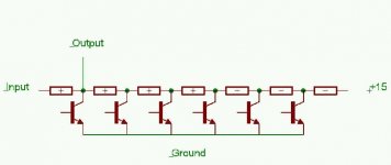
BJT volume control.
Here is a thread I posted a while back on a similar subject,
http://www.diyaudio.com/forums/showthread.php?threadid=39700&highlight=BJT+Volume
The circuit I have shown there worked very well in simulations but I didn't take it any further, instead I have built a pre-amp using relays for the volume control.
Anyway I thought that could be of interest. I don't know if it is at all similar to the design in the Aleph pre-amps.
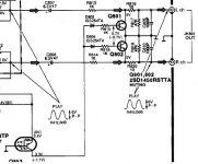
There are a couple of things in the design I have posted that may not be obvious.
Firstly when the NPN devices shunting the signal path are switched on the base current must be high enough such that it exceeds the maximum possible absolute value of the collector current.
When the NPN devices are switched off the base voltage must be lower than the minimum signal level appearing at the collector. Hence I have shown in the design that the bases get pulled to the -15v supply rail by resistors.
Here is a thread I posted a while back on a similar subject,
http://www.diyaudio.com/forums/showthread.php?threadid=39700&highlight=BJT+Volume
The circuit I have shown there worked very well in simulations but I didn't take it any further, instead I have built a pre-amp using relays for the volume control.
Anyway I thought that could be of interest. I don't know if it is at all similar to the design in the Aleph pre-amps.
There are a couple of things in the design I have posted that may not be obvious.
Firstly when the NPN devices shunting the signal path are switched on the base current must be high enough such that it exceeds the maximum possible absolute value of the collector current.
When the NPN devices are switched off the base voltage must be lower than the minimum signal level appearing at the collector. Hence I have shown in the design that the bases get pulled to the -15v supply rail by resistors.
maik said:What about the following circuit. Think about R1 as a
large shunt resistor (let say 10k). The subsequent
resistors may define a divider ratio for input/output
as you like. The last resistor connects to a positive
supply. It can also be a current source. The control
logic must ensure, that at least one BJT is conducting.
It will create a voltage devider for the input signal
and it will be biased by the current defined by the
resistor network and the positive supply.
just a thought-regarding symmetrical inputs-it's better to have attenuator arranged in shape of two series resistors and one shared shunt element(s);
positive and negative legs are virtual grounds ..I know that this is obvious (and really have no time to further investigate actual topic on the bench) ,but-just as agenda......
- Status
- This old topic is closed. If you want to reopen this topic, contact a moderator using the "Report Post" button.
- Home
- Amplifiers
- Pass Labs
- Technique behind Aleph X0.2 Volume Control