Yes it happened!!! I gave my friends who are in the electronics industry here in Silicon Valley a list of cool parts I expected them to get for me cheapo or free. This was precipitated by me seeing a business card from a friend with the Vishay logo!
Welll....... no luck for awhile, then I got some stuff - including these !!! YES !!a pair of Loveltech power jfets!!!
The DIY Audio equivalent of crack cocaine!
There is no way I can get more- I have already asked...
Even though I'm a mod, people that have gotten to know me online realize that I am a mod more because of my enthusism for cruelly mistreating misunderstood members than my technical chops.")
So far I've made some speakers, some ambitious and some not, a few chip amps, and have been working on about the simplest amp in the universe- the Pass SOZ, for about 3 years now...Hey!, it requires a pretty sturdy setup for all those heatsinks!
1. So, I've got 2 of the these and it looks like I only need one per channel to get 15 watts?
2. Can I use one IRF P140 per channel as Q2?
3. Can I use an unregulated power supply with a pi filter putting out 50v to run it?
4. I'm planning to make the circuit on perf board, then attach it to a heatsink. Another idea is to have the power devices separate from the rest of the circuit by about 6".
Is this OK? Should the resistor r4 be kept close to Q2?
Helppp me!!! I'm sure I will make mistakes that will spare you from making the same! We can accumulate construction info here, and when your ship (full of jfets) comes in, you will be ready to go!
thanks,
Mark
Welll....... no luck for awhile, then I got some stuff - including these !!! YES !!a pair of Loveltech power jfets!!!
The DIY Audio equivalent of crack cocaine!
There is no way I can get more- I have already asked...
Even though I'm a mod, people that have gotten to know me online realize that I am a mod more because of my enthusism for cruelly mistreating misunderstood members than my technical chops.
So far I've made some speakers, some ambitious and some not, a few chip amps, and have been working on about the simplest amp in the universe- the Pass SOZ, for about 3 years now...Hey!, it requires a pretty sturdy setup for all those heatsinks!
1. So, I've got 2 of the these and it looks like I only need one per channel to get 15 watts?
2. Can I use one IRF P140 per channel as Q2?
3. Can I use an unregulated power supply with a pi filter putting out 50v to run it?
4. I'm planning to make the circuit on perf board, then attach it to a heatsink. Another idea is to have the power devices separate from the rest of the circuit by about 6".
Is this OK? Should the resistor r4 be kept close to Q2?
Helppp me!!! I'm sure I will make mistakes that will spare you from making the same! We can accumulate construction info here, and when your ship (full of jfets) comes in, you will be ready to go!
thanks,
Mark
I think it's imperative that the first thing you do is send the jfets to me for testing. This, of course, so you know your devices are good. I'll simply reply by email to let you know if they work or not.
Naw, We have much more comprehensive semiconductor testing facilities here in Utah.. cause of Hill AFB. I suggest you send them to me for a more comprehensive run down on them than the guy from Massachucets can give you... I am also closer to you so you'll know faster. I will also reply quickly by E-mail so you know exactly whats with them and where they've gone to(or into).....
Mark
All very generous offers-typical of the selfless spirit here on DIY Audio!
If they are bad it would be a problem, but I'm counting on you guys getting the order in soon so worst case I'm ready for their arrival. I promise to give you guys a report on how utterly fantastically GREAT they sound!
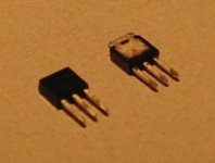
Here's a blurry photo showing the devices to prove I'm not making this up.. They DO need to be clamped or something to attach them to a heatsink...
I am looking forward to answers to my questions- I have plenty more...
If they are bad it would be a problem, but I'm counting on you guys getting the order in soon so worst case I'm ready for their arrival. I promise to give you guys a report on how utterly fantastically GREAT they sound!
Here's a blurry photo showing the devices to prove I'm not making this up.. They DO need to be clamped or something to attach them to a heatsink...
I am looking forward to answers to my questions- I have plenty more...
Attachments
Variac said:my enthusism for cruelly mistreating misunderstood members
Speaking about swine throwing pearls.
Well, I DON"t think I mistreat people actually- Its just the ones taking the "long vacation" that seem to express this opinion
Then again, my avatar seems to fit.
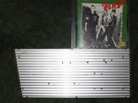
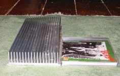
Here is an example of some heatsinks. I was planning to use one for each channel of the amp Nelson describes with one jfet and one mosfet. The power resisters will be lightbulbs so not on the heatsink.
Is that gonna be enough?
Then again, my avatar seems to fit.
Here is an example of some heatsinks. I was planning to use one for each channel of the amp Nelson describes with one jfet and one mosfet. The power resisters will be lightbulbs so not on the heatsink.
Is that gonna be enough?
Attachments
Its just the ones taking the "long vacation" that seem to express this opinion
What ever happened to Fred anyway?
Congrats on getting your hands on the holy crown jewels of DIY audio - I would love to offer you testing of your devices under extreme climate conditions here in the cold scandinavia, but sadly, I have no time due to my masters assignment, so you'll have to do with mark or mpmarinos offer ;-)
About the heatsink, I think you should consider cutting it in half - assuming the fins wil be vertical, thus giving you a sink that is twice your present hight - I write this, based on a suggestion I got when asking the same question as you, just for a A30 - to look at some graphs over heatsinks, that shows hight and cooling effect - about 15 centimeters the efficiency declines very, very rapidly. A heavy duty alu cabinet to mount the sinks on, will also help the amps contribution to the global warming.....
Or mabye a slow running fan, should your test run of the amp prove to hot ?
Cheers !
Buhl
Buhl said:
About the heatsink, I think you should consider cutting it in half - assuming the fins wil be vertical, thus giving you a sink that is twice your present hight - I write this, based on a suggestion I got when asking the same question as you, just for a A30 - to look at some graphs over heatsinks, that shows hight and cooling effect - about 15 centimeters the efficiency declines very, very rapidly. A heavy duty alu cabinet to mount the sinks on, will also help the amps contribution to the global warming.....
Or mabye a slow running fan, should your test run of the amp prove to hot ?
Cheers !
Buhl
even better solution is to cut each of your Jfets in two (halfs,off course) and spread them on each end of heatsink;
in that case-results will be ,in worst case, same as you manage to send them to me for testing
Mount a big power transistor over the second from right center hole in this picture:
http://www.diyaudio.com/forums/attachment.php?s=&postid=778079&stamp=1133239696
Rotate the sink 90 degrees clockwise from picture perspective and theta Z.
Drive the transistor at 52 watts and see if you like the temperatures you get after things level off. Given that aluminium has almost the specific heat of water, it will take a good half hour or so.
I think that you would like to give that whole thing to the IGFET and find something with about 4X the resistance to air just for the JFET, thermally isolated from IGFET sink, giving you the option to run lower case temperature for the JFET, which I would prefer.
If you're using the Pass circuit there's about 7 watts in the JFET and 45 in the IGFET. If you put it all on that sink you'll probably get about a 40C rise on that sink.
The fin pitch it's using would Really prefer a gentle breeze. If somebody were to produce some 10 CFM 120mm fans with totally noiseless commutators and precision bearings they could make a mint in the hi-fi audio market.


Andrew- thanks for the advice. Especially about the watts needing to be dissipated for the 2 components. I am using the Pass circuit. I suspect he will update it at some point, but then I'll update my circuit!
I am glad you mentioned separate sinks for the JFETs . I was planning to do that but thought that maybe I was being too cautious.
I believe that you have a half hour to edit your messages. There is an "edit" button to the lower right of your post for this time.
I am glad you mentioned separate sinks for the JFETs . I was planning to do that but thought that maybe I was being too cautious.
I believe that you have a half hour to edit your messages. There is an "edit" button to the lower right of your post for this time.
If I would have realized my mistakes And known of the editing function soon enough I could have saved us all the irritation. Sometimes I start thinking real fast without actually thinking. Especially when yapping about something that used to be familiar but ain't really so much lately.
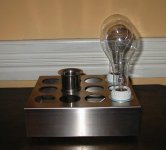
ok, here is one of the monoblock chassis-no electronics yet.
I got the bulbs at an electrical supply house as Nelson recommends.
I had to wait ''til a clerk could take me down to the deepest basement and look through boxes of old bulbs. 300 watt incandescent bulbs aren't really used much anymore, except halogen ones, and I wanted the "classic bulb look". Anyway, we found 4 good ones at $4 ea.
As with all DIY, it is all the additional parts that add up. The ceramic sockets were another $4 each.
Attachments
Variac said:ok, here is one of the monoblock chassis-no electronics yet.
it's a beauty! great work so far!
Thanks guys,
The stainless box was sold as a spice rack. It hangs vertically on the wall and had all the holes to slide cylindrical spice jars into. I found it a a sidewalk sale and bought the pair for $3 with a future chassis in mind. I will cover the open holes with a piece of mesh below.
Blues, it is a velocity stack that I had two of sitting around for years. They are so pretty I wanted to save them for something special.
From a Weber or Dellorto carb. It fit perfectly in one of the holes in the chassis. It has no function and could be placed in any other hole!
Please help me think of a use! I guess a heat sink could be under it, but it extends into the box at least an inch so there isn't much room under it.....
- Status
- This old topic is closed. If you want to reopen this topic, contact a moderator using the "Report Post" button.
- Home
- Amplifiers
- Pass Labs
- Pass JFET Amp- I'm making one!