Re: Not a clue
I couldn't find a better cap for 10pF value in parallel with 100k ohm in a feedback loop.")
HarryHaller said:Say are those aqua colored caps ceramics?
H.H.
I couldn't find a better cap for 10pF value in parallel with 100k ohm in a feedback loop.
I have to agree with H Potter that point to point wiring is a fine way to build something in small quantities. I've worked in the microwave field for 30 years and have prototyped tons of designs
using point to point (albeit very short distances) wiring over a continuous ground plane. The technique works well up to about a couple of gigahertz where the transition from lumped elements to tranmission lines starts to become necessary.
In fact when comparing the performance of designs implemented on a PCB to the point to point technique (especially when the circuit impedances are high), the point to point technique usually results in superior performance. This is mostly due to the higher loss of the PCB dielectric and built in stray capacitance
. At audio frequencies I suppose the additional capacitance inherent in PCB runs can contribute to some signal degradation. Looking at it another way the dielectric constant of air is 1, Glass epoxy=5, even teflon is 2.2. A Lower dielectric constant yields a smaller capacitance for a given trace to ground plane spacing.
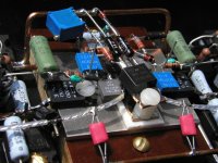
That's the close up of front end. I mounted differential mosfets on metal plate and current source mosfet is suspended above. Two green power resistors are the outputs to ground 30 ohm. You can also notice that I used 0.1ohm Caddock resistor at the output. It's 16W and it compact size really fits my setup. I also thin it souns much better than the bunch of parallel resistors. Everything could be so close together that signal traces are practically not existant. I'm really curious about the sound, but still second channel and PS have to be done.
Attachments
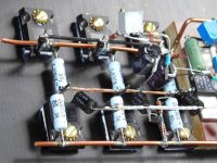
And the final picture shows how the output mosfets are connected. You really don't need the PCB for that stage, everything fits together and locks in place. By using PCB I would introduce unnecessary connections and longer signal paths. You can see the sensing circuits hanging between the rails. I had pretty hard time puting current sense circuit together but finally I manage to make it compact. That's the place for those circuits, beside output devices and not on the front end board. Grey, you can see that I'm also using Panasonic blue power resistors. With so many of them in the output I would be hard pressed to spend money on anything more expensive. And thank you for the Aleph X circuit.
Attachments
Swapping components and some minor circuit changes are much easier with a PCB.
Hpotter, your amp is one of the cleanest complex P2P implementations I've seen. Without a lot of care (and a simple enough circuit) P2P can quickly become such a mess that even identifying which part of the circuit is what is a real pain.
I always use P2P wiring in PSU where large currents are flowing, and I've certainly built many other circuits that way, but all things being the same I'd much prefer a board. Sometimes it just takes too long to design and etch one, or the compromises required to obtain a planar mapping are too great.
Stray capacitance on PCBs is a problem, but not of great effect on a well designed PCB at audio frequencies. The impedence of a trace with Cp=100pF at 100kHz is 16M. Where stray capacitance has a chance to cause great harm (feedback loop, miller effect) extra steps can be taken to reduce crosstalk (guard traces) or trace-to-ground capacitance (unfilled or no ground plane). Sometimes stray capacitance can be exploited for HF rolloff, as it is nearly an ideal capacitance.
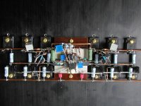
With PCB I wouldn't achieve such tight component spacing which led to very short signal paths, especially in the input and sense circuits. Period.
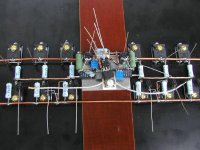
My intention was to make a circuit superior to PCB, that's why it also looks organized and pleasing. Took me two days to do it, but taking into account that my previous amps stayed in my system 7 years it's not such a big effort or waste of time.
Also, that amp is based on the current production design from Pass Labs and I thought that making PCB would be inappropriate.
I thanked Grey already, but I'd also like to give my thanks to Mr. Pass for providing him and everybody else on this forum with inspiration.
With PCB I wouldn't achieve such tight component spacing which led to very short sign
You go for it..... PC boards are for sissies and mass production. Vectorboard works great also and is a little friendlier for the less adventurous. Point to Point sounds better. Carefull with those scope probes and VOM leads though.
H.H.
You go for it..... PC boards are for sissies and mass production. Vectorboard works great also and is a little friendlier for the less adventurous. Point to Point sounds better. Carefull with those scope probes and VOM leads though.
H.H.
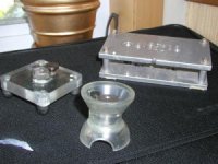
No, those screws require the threaded hole. You can drill straight holes on table drill or you can use the drill guiding blocks like I'm using. Two of them are commercial pieces, used in aircraft industry, the third one is home made. I also use them for tapping the holes. As I said before cordless drill gun with a clutch works the best here.
- Status
- This old topic is closed. If you want to reopen this topic, contact a moderator using the "Report Post" button.
- Home
- Amplifiers
- Pass Labs
- The beaty of p2p wiring