I don't see any errors in the topology, and it looks like
you have about 40 dB open loop. The values that you
have would be similar to a first effort I would make with
this circuit, but you'll want to assume that you end up
tweaking it.
I think you'll want to have good regulation on the supplies
for noise, as the chip amps are referencing both the
negative supply and ground.
At the first time I would make Aleph 3 but when I considered the schematic I thought that I must pay a lot of money for Aleph 3 making. So I have to modify it by using output stage is chip amps.

I think so. I don't also see any error on schematic.I don't see any errors in the topology
I agree with you for power supply. Now I have no idea for power supply.I think you'll want to have good regulation on the supplies
Yes, I have.
The regulator using the LM338 chips works quite well. It has one minor limitation: if you have a high VA rated transformer (500VA or larger), and a lot of capacitance after the regulator (more than 10,000uF or so) then the inrush current surge can overlaod the regulator chips. Otherwise it works very well.
I have tried variations of the other discrete regulator circuit from that page, and thought they perform better than the LM338 regulators, they also require a much larger unregulated to regulated voltage drop.
Lastly, have a look at the Zen articles, where Nelson presents some simple zero feedback regulators that I have also used to great effect as well in my headphone amp adventures.
Good luck.
This field is a new for me. In currently, I try to study the amplifier which are designed by transistor and MOSFET. I used to study electronic devices so long time.
For regulation, I think so, I will use LM338 for this amplifier. I thought that I will not be able to use the easy regulation like GC for this amp.
For regulation, I think so, I will use LM338 for this amplifier. I thought that I will not be able to use the easy regulation like GC for this amp.
3875 VS 3886
Have you picked a winner yet Mr. Pass?
Anybody else want to throw their two cents in?
Nelson Pass said:I have a couple more for you today, Brian. I believe they
will address some of these issues.
I don't personally know that the 3886 is better sounding than
the 3875, but I would would bet that it is based on the data
sheets: Lower open loop gain, higher bias, smoother spectral
distortion plots. I'll let you know when I've had the time to
play with them properly.
Have you picked a winner yet Mr. Pass?
Anybody else want to throw their two cents in?

Re: 3875 VS 3886
I have not, not having had the time to play, but if I were to
judge from the data sheets, I would pick the 3886 based on
the look of the curves and the lesser feedback. This is, of
course, pure speculation on my part. Eventually I'll get around
to building both up, as I bought a couple hundred parts.
Gaucho said:Have you picked a winner yet Mr. Pass?
I have not, not having had the time to play, but if I were to
judge from the data sheets, I would pick the 3886 based on
the look of the curves and the lesser feedback. This is, of
course, pure speculation on my part. Eventually I'll get around
to building both up, as I bought a couple hundred parts.
I also never tried to compare the both eventhough I have LM3886. At the first time I bought LM3886 for my next amp. because I know LM3875 will be discontinuous ICs in soon.
For my amplifier I will try LM1875 for testing first because in my country LM3875 or LM3886 are as expensive as LM1875.
For my amplifier I will try LM1875 for testing first because in my country LM3875 or LM3886 are as expensive as LM1875.
From my simulation result at high frequency (20kHz), I found something strange as two attached pics, result1 indicates overall of output signal, result2 indicates only red region in result1. I have no idea for this case. Could anyone tell me how to solve this problem?
Attachments
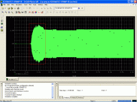
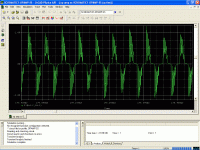
Looks like oscillation. Think in terms of RC networks to ground
at the outputs of the chips, and throwing away some of the
gain in the chips using voltage dividers on their + inputs and
greater gain loops into their - inputs.
Also, stop trusting simulators so much - the map is not the
territory.

at the outputs of the chips, and throwing away some of the
gain in the chips using voltage dividers on their + inputs and
greater gain loops into their - inputs.
Also, stop trusting simulators so much - the map is not the
territory.
I feel that more and more DIYers here just making simulations only, not heating up their solder iron. Try it with pin to pin experimental cct. It's really fun knowing what different cct makes different sound.Also, stop trusting simulators so much
Hi lumanauw,
The simulation can indicate you in the future results of circuit. If there are something mistake or strange, you will be able to revise them immediately. For new design, I will simulate it first before I actually build it.
I don't trust in simulation so much but it's a tool that makes me convince in that model.
Which parts should be thrown away?To throw away open loop
Did you mean the circuit has to add a resistor at output?load the outputs with some resistance
Thank you for the suggestion. Now I'm try to make its PCB.
gencard,
Although nar's suggestion does reduce the open loop gain, to eliminate the stability problem in this design requires the gain to be reduced after the differentail pair and before the opamp. This is achieved by increasing the ratio of resistance of R1:R13 and R23:R17 in your schematic (i.e. increasing the values of R1 and R23 to 10k throws away 6dB open loop gain).
Cheers,
Terry

- Status
- This old topic is closed. If you want to reopen this topic, contact a moderator using the "Report Post" button.
- Home
- Amplifiers
- Pass Labs
- GC SuperSymmetry