Azamkita,
To my knowledge I am the only one so far that has built the circuit with the values that I posted. Those are the values that I arrived at by incrementally "throwing away gain" until the circuit stopped oscillating without an input signal. I don't think that Nelson has had a chance to do any experimenting with this circuit yet.
jh6you,
My circuit to date does not have a zobel, but as it has continued to burn in the sound has become fuzzy suggesting that the zobel is indeed required (Not that there was any doubt after Nelson's recommendation!). I will be adding the zobels this weekend.
Terry
Fundamentally, you don't want to operate a chip amp without
an output RC network to ground. The open loop gain is just
too high and the phase margin too low to practically avoid it.
Even if you don't see oscillation in the output, you can often
hear the effects of circuits which are just barely stable - so
we use "Zobels" and throw away some open loop gain to
ensure what I think of as "relaxed" performance.
Hi Metalmen,
Just to try. I build one as your circuit but with following changes.
1) LM3875 ==> TDA2030A
2) +/-30V ==> +/-18V
3) ZTX450 ==> MPSA42
I use single ended input and grounded the other input. Loudspeaker connected to both differential ouput. Problem is no sounds coming out from the amp.
Pls advise.
Just to try. I build one as your circuit but with following changes.
1) LM3875 ==> TDA2030A
2) +/-30V ==> +/-18V
3) ZTX450 ==> MPSA42
I use single ended input and grounded the other input. Loudspeaker connected to both differential ouput. Problem is no sounds coming out from the amp.
Pls advise.
My circuit to date does not have a zobel, but as it has continued to burn in the sound has become fuzzy suggesting that the zobel is indeed required (Not that there was any doubt after Nelson's recommendation!). I will be adding the zobels this weekend.
Terry, did adding a Zobel cure the fuzziness?
Ipanema,
My off-the-cuff thoughts are that the MPSA42 should susbstitute with no problems, and although I am not familiar with the TDA2030A it should be possible to substite a wide variety of op-amps into the circuit. It should also be possible top run the circuit from a fair range of voltage rails, although different rail values may require some minor tweaking on values in the CCS. My overall experience has been one of getting rid of too much sound (i.e. oscillation noise) rather than no sound. I'd start by checking the CCS that bias the differential pair and make sure that it is providing current. Next, check the DC offset across the outputs, and then check if there is any DC voltage from each output terminal to ground. I'll think on this a bit more and see what I come up with, in the meantime get out eh ol' voltmeter and check to see what the DC voltage values are at different points in the circuit to provide a few more clues.
Gaucho,
I added the Zobel, and it made a marked improvement in the fuzzines factor, but did not entirely eliminate it.
In the meantime, due to a "lack of the right tool" problem, which will be remedied tonight (local tool shop tells me my order will arrive today), I haven't completed my modified BZLS to try driving the amp balanced. I believe that Nelson has indicated that SUSY only makes a difference when driven by a balanced signal.
One other thought did occur to me, which is that I have been testing with only a 20kohm stepped attenuator between the amp and the CD player. This amp has a relatively low input impedance compared to standard gainclones, and I have begun to wonder if my CD player has enough drive for this passive approach to volume control with this circuit. To sort this out I will try driving the amp from the preamp-out of my Rotel integrated and see if this makes any difference and report back tomorrow.
Another possibility is that, although I am certain the amp circuit as I last posted it is stable with no input signal, it may be necessary to throw away yet some more gain between the differential pair and the chips to keep it stable when a signal is present. This is where I really wished I owned an oscilloscope! I also want to try reducing the capacitance on the chips power connections (currently 1500uF caps) and see if that makes any difference.
Unfortunately my wife has been quite ill over the past few months so the availability of playtime to work on this project has been severely curtailed. It may take me awhile yet to work through the troubleshooting to figure everything out, but I am far from giving up on it. I apologise for taking sooooooo long in developing this, but I will get there ... eventually!
Cheers,
Terry
Hi metalman,
Thanks for you answer. From measurement, the tail current is 3.9mA. Is it OK?
The output DC voltage (differential) is <5mV. But still no sounds. I can only hear some soft high frequency hum. Do you have any idea what's wrong with this? Or what should I measure to rectify the problem?
Regards
Thanks for you answer. From measurement, the tail current is 3.9mA. Is it OK?
The output DC voltage (differential) is <5mV. But still no sounds. I can only hear some soft high frequency hum. Do you have any idea what's wrong with this? Or what should I measure to rectify the problem?
Regards
metalman said:[snip]
No one will ever say this amp is warm sounding, however I personally don't find it to be so bright as to be harsh or unmusical.
...
and in comparison the X'ed GC sounds more detailed and dynamic, definitely cleaner, but at the same time less bright. Also, the bass from the X'ed amp is deeper and better controlled...
...
The X'ed GC looses warmth and is drier sounding in direct comparison to the Rotel.
looks like a true pass amp review ....
")
what would be the preferred way of connecting the amp, balanced with one signal carrier (no signal on cold), balanced/differential? does it matter at all in a supersymmetry amp like this (provided that the input levels are identical)?
Inverting GCs?
Anyone considered running the GCs in the inverting configuration and just swap diff amp collector connections? Scale R11, 12, 13, and 14 to raise impedance in inverting config. Stability will have to be revisited.
Why not throw away gain through emitter degeneration in diff amp? This should help linearity and stability.
Thoughts?
Pete B.
Finally got around to trying my amp driven from the pre-out of my Rotel integrated last night, and I am happy to report that the remaining fuzziness that I earlier reported has been eliminated. The conclusion from this little experiment is that the input requires a modicum of current, more than some CD players can deliver.
There are some other changes in the sound that have occurred as well. While still not a warm sounding amp by any means, the brightness I originally reported has smoothed out to a large degree, making it more pleasant to my ear. I can't say whether the change resulted from the addition of the Zobel or from connecting it to a proper preamp, but it is definitely less hard sounding, and at the same time the soundstage actually seems better focused.
Next experiment for me is to drive the amp with a balanced signal, hopefully this coming weekend (my CC-CCS-X-BZLS is nearly finished!!!).
Those numbers look good. Next measure the voltage from the output of one of the chip to ground (Yes, this is a strange measurement to ask for, but with his amp I have found it can be quite useful). Next lets make sure the signal is being communicated from the differential pair to the chips by measuring the DC voltage across C1 and C2 (referring to my last posted schematic), which in your circuit should be about 12V. Also check the voltages across R1 and R2 to see if the current is being evenly divided. If all looks good from those we'll try a few more checks elsewhere.
The best signal connection for the amp is a true balance signal (signal on hot, inverted signal on cold). Nelson's whitepaper on supersymmetry shows a few graphs demonstrating that the benefit of supersymmetry is only realized when driven by a balanced signal. It can be run from a single ended signal, provided that you connect the negative input to ground, which is what I have been doing to date.
I don't see any reason why an inverted configuration shouldn't work. Give it a try! As to the emitter degeneration, that can be done, but will also somewhat reduce the supersymmetric effect, depending of course on how much degenration is used.
Cheers, Terry
There are some other changes in the sound that have occurred as well. While still not a warm sounding amp by any means, the brightness I originally reported has smoothed out to a large degree, making it more pleasant to my ear. I can't say whether the change resulted from the addition of the Zobel or from connecting it to a proper preamp, but it is definitely less hard sounding, and at the same time the soundstage actually seems better focused.
Next experiment for me is to drive the amp with a balanced signal, hopefully this coming weekend (my CC-CCS-X-BZLS is nearly finished!!!).
Originally posted by Ipanema
From measurement, the tail current is 3.9mA. Is it OK? The output DC voltage (differential) is <5mV.
Those numbers look good. Next measure the voltage from the output of one of the chip to ground (Yes, this is a strange measurement to ask for, but with his amp I have found it can be quite useful). Next lets make sure the signal is being communicated from the differential pair to the chips by measuring the DC voltage across C1 and C2 (referring to my last posted schematic), which in your circuit should be about 12V. Also check the voltages across R1 and R2 to see if the current is being evenly divided. If all looks good from those we'll try a few more checks elsewhere.
Orignially posted by matjans
what would be the preferred way of connecting the amp, balanced with one signal carrier (no signal on cold), balanced/differential? does it matter at all in a supersymmetry amp like this (provided that the input levels are identical)?
The best signal connection for the amp is a true balance signal (signal on hot, inverted signal on cold). Nelson's whitepaper on supersymmetry shows a few graphs demonstrating that the benefit of supersymmetry is only realized when driven by a balanced signal. It can be run from a single ended signal, provided that you connect the negative input to ground, which is what I have been doing to date.
originally posted by PB2
Anyone considered running the GCs in the inverting configuration and just swap diff amp collector connections? Scale R11, 12, 13, and 14 to raise impedance in inverting config. Stability will have to be revisited.
Why not throw away gain through emitter degeneration in diff amp? This should help linearity and stability.
I don't see any reason why an inverted configuration shouldn't work. Give it a try! As to the emitter degeneration, that can be done, but will also somewhat reduce the supersymmetric effect, depending of course on how much degenration is used.
Cheers, Terry
LM1876
Hi,
I built one with two LM1876, one per channel.
The LM1876 is a stereo amp, 2x20W.
It has a maximum of 64V supply voltage so I use a 2x15V transformer to get about 2x20V. Probably a bit low?
The sound is not bad, bass is probably even better than my 30W-aleph-X, but it can't really compete in resolution.
Has anyone experience with this chip?
How much better are the 3876 or 3886 chips?
Is there probably an advantage in using a stereo chip because the two amps are "more equal"?
m.
Re: LM1876
One nice thing about using a stereo amp is that you can run it in parallel. This will give you more current to run lower impedence loads. You can also run it bridged, giving you more power. Come to think of it, the LM4780 would be an excellnt cantidate for X'ing, as it has two comlete LM3886 chips in it. Add the surrounding circuitry and you have a nice, compact X'ed chip-amp. This really gives me something to think about. Any thoughts Mr. Pass?
Cheers,
Zach
dieringe said:Hi,
Is there probably an advantage in using a stereo chip because the two amps are "more equal"?
m.
One nice thing about using a stereo amp is that you can run it in parallel. This will give you more current to run lower impedence loads. You can also run it bridged, giving you more power. Come to think of it, the LM4780 would be an excellnt cantidate for X'ing, as it has two comlete LM3886 chips in it. Add the surrounding circuitry and you have a nice, compact X'ed chip-amp. This really gives me something to think about. Any thoughts Mr. Pass?
Cheers,
Zach
dieringe,
Congratulations on achieving a working X'ed chip amp. I very much envy you, as I do not have (yet) an aleph or other comparable amp for comparison with my creation. But I am very much encouraged to see others trying out this approach. I believe that much can be accomplished with this approach but that it will require a group effort to sort out all the details.
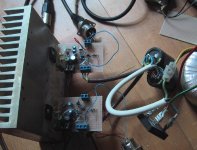
My only suggestion at this time for an avenue for possible improvement lies with the power supply. The LM chips seem to interact actively with the power supply, and I believe that the key to getting the max performance will lie in optimizing that interface. Right now I am using an LM338 regulator based power supply. From your pictures it looks like you are using strictly capacitive PS filtering, could you provide some details on your power supply arrangement.
Glad to have a fellow experimenter on this path,
Terry
Congratulations on achieving a working X'ed chip amp. I very much envy you, as I do not have (yet) an aleph or other comparable amp for comparison with my creation. But I am very much encouraged to see others trying out this approach. I believe that much can be accomplished with this approach but that it will require a group effort to sort out all the details.
My only suggestion at this time for an avenue for possible improvement lies with the power supply. The LM chips seem to interact actively with the power supply, and I believe that the key to getting the max performance will lie in optimizing that interface. Right now I am using an LM338 regulator based power supply. From your pictures it looks like you are using strictly capacitive PS filtering, could you provide some details on your power supply arrangement.
Glad to have a fellow experimenter on this path,
Terry
- Status
- This old topic is closed. If you want to reopen this topic, contact a moderator using the "Report Post" button.
- Home
- Amplifiers
- Pass Labs
- GC SuperSymmetry