Dear Mr Pass
as a newbie to audio, and having read some of your articles on the PassDIY page, i would just like to say thank you for writing such insightful articles...i do have a small question though...i was just reading the article on the A75, and i was wondering what this folded cascode arrangement is...i am referring to the series combination of cap and resistor at the tails of the dual diff pairs...and also, how do you determine the gain that is required?
as a newbie to audio, and having read some of your articles on the PassDIY page, i would just like to say thank you for writing such insightful articles...i do have a small question though...i was just reading the article on the A75, and i was wondering what this folded cascode arrangement is...i am referring to the series combination of cap and resistor at the tails of the dual diff pairs...and also, how do you determine the gain that is required?
You can set up the A75 for a conventional voltage gain
stage on the second stage, or you can set it up as a
folded cascode, loosely defined as a cascode circuit which
also functions as a level shifter. You can find out more from
the www.passdiy.com (or) www.passlabs.com article from
Audio magazine on cascoding.
In any case, the folded cascode has a lot less open loop gain
than the conventional common-source arrangement, but is
very fast and stable. The output current variation is equal to
the output current variation of the diff pair, so in that sense
you can think of it as a current mirror with unity gain.
I tried to understand folded cascode, if the differential is running at very low current (Mr.Pass uses it at high differential current). If the differential is running at 2mA ccs (1mA each leg at steady state), I assume each leg is capable of 0-2mA (if the other differential leg is on or off).
Putting folded cascode (set the bias about 10mA), that means the level shifter stage can be 8-10mA. The difference is the same as in the differential, 0-2mA.
What is really important in the level shifter stage, is it the bias (big enough, 10mA) or the difference current (only 0-2mA).
In the ordinary common emitor VAS, the swing can be anywhere from 0-bias, but in this folded cascode the swing is limited only to 0-differential current.
If the bias is high enough, but the swing is very little (the same as in differential) will it suffice to drive the current amp stage?
You can set the level shifter at any bias current you want, but
if you set it up to deliver AC than the output of the diff pair,
it becomes a real gain stage.
I have a current working definition of what constitutes a
gain stage - it is a stage with voltage or current gain, and I
don't count cascodes with no current gain.
if you set it up to deliver AC than the output of the diff pair,
it becomes a real gain stage.
I have a current working definition of what constitutes a
gain stage - it is a stage with voltage or current gain, and I
don't count cascodes with no current gain.
Folded Cascode
Hi, Mr.Pass,
Why do people like to bias the VAS as big as possible, if less than that is enough? (in ordinary 3 stage configuration, not folded cascode configuration)
I follow the thread of x100 backengineered. Personally, I suspect that the bias in the differential =50mA dont have to be the same value in the folded cascode =also 50mA. They can be made different. But I dont see your comment on this. Are you using the same value or different value for differential and folded cascode?
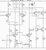
This opamp design is made by Sonnya. J1-4 is the output to the current stage. I see it as very clever opamp design. I made comment to this (in other thread) as a "SINGLE STAGE OPAMP", as I see it only have gain from differential. The folded cascode and current mirror dont have gain.
But Elso Kwak said "I think most of the gain comes from the current mirror loading the folded cascode....." What makes him see the cct that way?
Hi, Mr.Pass,
I see folded cascode has perspective of current swing transfer. If we use folded cascode, is it true that what is important for driving the next stage (in my example of 2mA diff and 10mA folded cascode) is it the small 2mA swing? The 10mA steady bias wont matter so much. If it is the 2ma swing who drive the next stage, how much mA swing will be sufficient?You can set the level shifter at any bias current you want, but if you set it up to deliver AC than the output of the diff pair, it becomes a real gain stage.
Why do people like to bias the VAS as big as possible, if less than that is enough? (in ordinary 3 stage configuration, not folded cascode configuration)
I follow the thread of x100 backengineered. Personally, I suspect that the bias in the differential =50mA dont have to be the same value in the folded cascode =also 50mA. They can be made different. But I dont see your comment on this. Are you using the same value or different value for differential and folded cascode?
I hope you see current mirror also do not have gain.I have a current working definition of what constitutes a gain stage - it is a stage with voltage or current gain, and I
don't count cascodes with no current gain.
This opamp design is made by Sonnya. J1-4 is the output to the current stage. I see it as very clever opamp design. I made comment to this (in other thread) as a "SINGLE STAGE OPAMP", as I see it only have gain from differential. The folded cascode and current mirror dont have gain.
But Elso Kwak said "I think most of the gain comes from the current mirror loading the folded cascode....." What makes him see the cct that way?
Attachments
Re: Folded Cascode
"I see folded cascode has perspective of current swing transfer. If we use folded cascode, is it true that what is important for driving the next stage (in my example of 2mA diff and 10mA folded cascode)"
Yes, the swing of the diff pair is that will determine the output
of the cascode, since the cascode has no current gain.
"The 10mA steady bias wont matter so much. If it is the 2ma swing who drive the next stage, how much mA swing will be sufficient?"
It is always good to bias a folded cascode transistor at somewhat
higher than the swing of the diff pair, to prevent it from
contributing nonlinearity. 2 mA from the diff pair is not very much,
but that whether it's enough depends on the load. I like to
use higher figures when using folded cascode in power amps.
"Why do people like to bias the VAS as big as possible, if less than that is enough? (in ordinary 3 stage configuration, not folded cascode configuration):
High bias on the VAS improves its linearity, and provides more
current to drive the load.
"I follow the thread of x100 backengineered. Personally, I suspect that the bias in the differential =50mA dont have to be the same value in the folded cascode =also 50mA. They can be made different. But I dont see your comment on this. Are you using the same value or different value for differential and folded cascode?"
See above
"But Elso Kwak said "I think most of the gain comes from the current mirror loading the folded cascode....." What makes him see the cct that way?"
If the output of the current mirror is loaded with high impedance,
then it will deliver voltage gain, even if it is set for unity current
gain.
Hi, Mr. Pass,
So, current mirror can make voltage gain, even if the current gain is 1.
If the output is between collectors (like the sch of Sonnya), I think even if the current swing is as low as 0.01mA, it should be able to have full voltage swing between rails, the problem is how much mA is enough for driving the next stage (like my question above)
So my view of Sonnya's opamps is wrong. It is true that it has no current gain, but it does make voltage gain. How to calculate voltage gain in this folded cascode design?
Is there any formula for determining this load figure? How about if the current stage is bipolar darlington and the other is vertical mosfets. Will they differ in current swing they need? I dont know how much is enough, since I am really new with this folded cascode, but very interested.2 mA from the diff pair is not very much, but that whether it's enough depends on the load. I like to
use higher figures when using folded cascode in power amps.
Is it high or low impedance? How to determine input impedance of current stage?If the output of the current mirror is loaded with high impedance, then it will deliver voltage gain, even if it is set for unity current gain.
So, current mirror can make voltage gain, even if the current gain is 1.
If the output is between collectors (like the sch of Sonnya), I think even if the current swing is as low as 0.01mA, it should be able to have full voltage swing between rails, the problem is how much mA is enough for driving the next stage (like my question above)
So my view of Sonnya's opamps is wrong. It is true that it has no current gain, but it does make voltage gain. How to calculate voltage gain in this folded cascode design?
Hi, Mr.Pass,
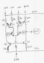
From Sonnya's design and your tutorial about low gain and folded cascode, I came up with this design. I wanted to use single differential, but I also likes pushpull VAS. In this design I could use folded cascode, but I choose current mirrors. The differential is working at low bias, 2mA, but from your opinion, the output stage must have more current. So in the final current mirror, I try to get different Re, 2K and 200ohm, so the final stage is bias at 10mA.
What is the good and bad thing about this design? Will the modified final current mirror gives full swing of 10mA (will it able to drive another current stage?)
Since there is somekind of current gain in the current mirror, will this still classified as low gain design (compared to ordinary 3 stage design)?
Attachments
Hi, all,
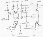
I made this design with perspective of current flowing, followed by voltage trace.
The current flows 2mA from CCS to differential, that is 1mA each to Q3 and Q5 (imagine reverse current flowing up from CCS to Q3 and Q5). Since Q3+Q4 and Q5+Q6 is current mirrors, there will be also 1mA flowing down from Q4 to Q7.
The base junction of Q3+Q4, Q7+Q8 and Q5+Q6 will be about (2kx1mA+0.6V=2.6V) relative to rail. Since the base of Q6 and Q8 is about 2.6V to rails, then the current flowing down from Q6 to Q8 is (2.6V-0.6V)/200ohm=10mA. (current mirrors is modified to current magnifier in Q5+Q6 and Q7+Q8)
Mr.Pass is right, if we wanted this cct tobe single action VAS, that is no need for Q3,Q4,Q7,Q8. Just replace the Q8 with CCS and it will work.
But since I wanted a push-pull VAS, then I use Q3,Q4,Q7,Q8 to perform "Pull" action by Q8, if Q6 is "Push" action. So the VAS will be push-pull, not single action by Q6+loaded by CCS (in the place of Q8).
Jam, you are right. This can easily modified to X configuration. Just use the principle of current mirrors, and we can get perfect balanced output by adding a transistor each besides Q4 and Q6, and make another set of Q7+Q8. It will be complete push-pull balanced VAS from single differential.
Q7 and Q8 are automaticly biased by forced current, that is 1mA for Q7 flowing down from Q4 and 10mA for Q8 by voltage+Vbe-drop from Q7P.S. I think that Q7 and 8 need to be biased though.
- Status
- This old topic is closed. If you want to reopen this topic, contact a moderator using the "Report Post" button.
- Home
- Amplifiers
- Pass Labs
- A75 question for Mr Pass