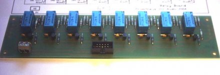
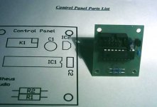
I just finished my PCB for a relay volume control.
This is only the relay board which only has the relays, resistors and driver circuits.
The Ralays here are the Takamisawa Relays at 12 Volts. The resistors are Welwyn low noise but very good priced.
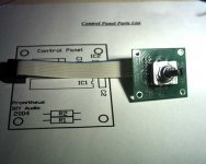
There is one more board with the PIC Microprocesor and encoder on it which looks like a small poti. I will be posting that soon. I don´t have the encoder yet.
What is very practical is that you can stack the relay pcbs to get as many channels as you want.
One board is for a stereo signal or one balanced signal. If you want to balanced signal like I will be using for the Balanced Line Stage then you can use 2 PCBs one on top of the other.
You can even use more pcbs for a surround volume.
More information will come soon.
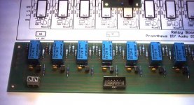
This is only the relay board which only has the relays, resistors and driver circuits.
The Ralays here are the Takamisawa Relays at 12 Volts. The resistors are Welwyn low noise but very good priced.
There is one more board with the PIC Microprocesor and encoder on it which looks like a small poti. I will be posting that soon. I don´t have the encoder yet.
What is very practical is that you can stack the relay pcbs to get as many channels as you want.
One board is for a stereo signal or one balanced signal. If you want to balanced signal like I will be using for the Balanced Line Stage then you can use 2 PCBs one on top of the other.
You can even use more pcbs for a surround volume.
More information will come soon.
For the microprocesor control and info you can get from TIll´s website here:
http://home.tu-clausthal.de/~tpa/relais/index.html
Till was kind enough to give 2 PICs so I could start this project.
I really want to thank him for his help.
The relay part is a bit different from Tills or from Nelson Pass´s.
It is a constant load attenuator. That means the load is always 5KOhms no matter what the setting.
I will find links and info on the subject.
Actualy you can find everything in this forum.
this is the thread with info.
http://www.diyaudio.com/forums/showthread.php?threadid=21198&highlight=
http://www.diyaudio.com/forums/showthread.php?threadid=21198&highlight=
Hi Till,
thanks for your nice words.
Without your help with the firmware my project would work in the first place. When I order some more boards I will give you some at cost price if you want.
Do you have done anything new with the firmware?
What I wanted to do is give the Volume control a display of some kind.
One idea is using 8 leds decoding the binary 8 bit code to decade.
Or a 7 segment led display.
Or the best but expensive a lcd display.
For the PCBs: I´m interested.
The firmware is slowly but still in development. http://home.tu-clausthal.de/~tpa/relais/software.html
For display: i simply have 8 LEDs in parallel to the drivers at PortB, and i see the volume in binary. No problem. For a LCD (price starts at 7€, i have some on hand) we would need more free pins, such a larger PIC. Else no problem. But i don´t know if its a good idea to have a LCD in the audio device - not really puristic and more RF noise. The pic with internal oscillator and such is choosen to have not to much noise in a minimalstic device. Of corse it would be possible to couple the PIC with a second one, controlling a display and remote reciver. I allready made a PGA2310 volume controll with LCD.
Yeah I have heard that LCDs have a lot of RF noise going out.
I like the idea of 8 leads around the volume knob. Not in Binary though, you and I could understand it but not everybody does lol")
I thought of making a pcb for the frontplate with 8 LEDS that take the 8-bit data and decode it into decade from 1 to 8. Actually to do that you need only the last 3 bits.
Another Idea I have heard but don´t really like is a bar of leds with 16 Leds using the last 4 bits.
I like the idea of 8 leads around the volume knob. Not in Binary though, you and I could understand it but not everybody does lol
I thought of making a pcb for the frontplate with 8 LEDS that take the 8-bit data and decode it into decade from 1 to 8. Actually to do that you need only the last 3 bits.
Another Idea I have heard but don´t really like is a bar of leds with 16 Leds using the last 4 bits.
till said:For the PCBs: I´m interested.
The pic with internal oscillator and such is choosen to have not to much noise in a minimalstic device.
Can you stop the clock on the pic you use? If so, you can stop the pic clock and awake the pic when pressing a button or remote input with an interrupt. I did that in my preamp, works fine.
There is one catch, it needs some time to wake-up. So you cannot decode the (e.g.) RC5 frame that comes in, but you have to wait for the second one to come by.
Regards,
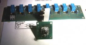
That´s correct. For balanced you need 2 boards.
I´m am now making the 2 board so I can test them together.
The problem with posting the boards is that I can´t convert the pcb or gerber files into pdf or jpeg.
If anybody has an idea how I can do that please help.
It´s not that I don´t want to post the pcb work.
I´m am now making the 2 board so I can test them together.
The problem with posting the boards is that I can´t convert the pcb or gerber files into pdf or jpeg.
If anybody has an idea how I can do that please help.
It´s not that I don´t want to post the pcb work.
- Status
- This old topic is closed. If you want to reopen this topic, contact a moderator using the "Report Post" button.
- Home
- Amplifiers
- Pass Labs
- Relay Volume Control for BLS