Did anyone notice this in the XA25 Manual?" Protection: Shutdown at 10 amps output"I can imagine putting a small resistance sense resistor on the drain of each output FET and having some kind of controller that shuts down the mains power when the AC voltage across any one of the sense resistor is Vsen-pp/Rsen > 10A*2.
A simpler way might be to use 2 triple-pole circuit breakers on the transformer secondary windings. The third poles are wired in series and shutdown all power using a latching relay on the mains.
Just guesses.
I generally discard all current protection circuitry.
In the past I have noticed Papa uses diodes for current limiting circuitry.
Alternatively you could do it like F6 supply where each channel has it's capacitance supply which is decoupled from the main bank with independent RC per channel.
Just turbo it a little more.
Just turbo it a little more.
I cannot find a 400W-600W power transformer 4x 22VAC secondaries. I can easily find what need with 2 secondaries.
Could you fit 2 x 300VA transformers in your case?
Richard Sumner could probably build you one with 4 secondaries at a fair price.
SumR - Richard Sumner Technology
Last edited:
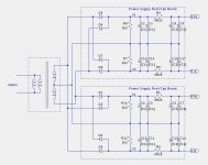
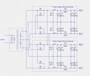
I have rectifier/cap boards as shown. I could cross connect the first stage capacitors as shown below. I do not have room for dual supplies. The other option is to use a 800W 4-secondary transformer. The 2nd image is power supply with 800W and 4 windings.
Attachments
Hi Lynn, could you manage a circuit with the wanted phase and gain margin?
This is about a good as I could get:
49ma FE bias
THD=.032% @100W 2R .024% @50W 4R .019% @25W 8R
-2dB @100kHz -3dB @133kHz H3@1W=.00013% DF=2500
input phase margin 36deg, gain margin 12dB
loop phase margin 52 deg, gain margin 11dB
44.3dB OLG 20dB CLG
THD=.032% @100W 2R .024% @50W 4R .019% @25W 8R
-2dB @100kHz -3dB @133kHz H3@1W=.00013% DF=2500
input phase margin 36deg, gain margin 12dB
loop phase margin 52 deg, gain margin 11dB
44.3dB OLG 20dB CLG
From the XA25 User Manual:
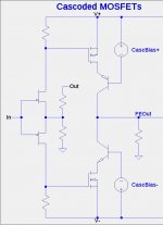
Cascoded MOSFET would imply the front end circuit topology shown below. Cascoding the MOSFETs would cut into the voltage headroom of FEOut which would be undesirable unless one was to increase the rail voltages.
My conclusion is that the XA25 User Manual statement was poorly worded and that the JFET drains are cascoded, not the MOSFETS.
Any other opinions?
"We still use the same “New Old Stock” of small power JFETs and cascoded MOSFET, in the classic “CFA” voltage gain circuit."
The term "cascoded MOSFET" is troubling me. All of Nelson's cascoded front-end circuits of which I am aware put the cascodes on the drains of the JFETs.
Cascoded MOSFET would imply the front end circuit topology shown below. Cascoding the MOSFETs would cut into the voltage headroom of FEOut which would be undesirable unless one was to increase the rail voltages.
My conclusion is that the XA25 User Manual statement was poorly worded and that the JFET drains are cascoded, not the MOSFETS.
Any other opinions?
Attachments
Yes I was thinking also many times about this and came to the conclusion that it was possibly not well expressed......
Mr. Pass did you write this?
😀😀
Mr. Pass did you write this?
😀😀
Would cascoding the second stage help to get lower output impedance?
Would it help to get higher bias current and less wattage at the second stage mosfets?
Would it help to get higher bias current and less wattage at the second stage mosfets?
No: The output impedance would be totally by the load resistor.
Yes: The power dissipation could be moved from the MOSFETs to the cascode BJTs.
Yes: The power dissipation could be moved from the MOSFETs to the cascode BJTs.
Here is another juzzle from the XA25 manual:
"The removal of this form of feedback is an important element in the performance of the XA25 and is accomplished by new approaches to stabilizing gain and bias of push-pull FETs."
What puzzles me is the word "gain" in "stabilizing gain and bias". I do not understand what is being stabilized or possible mechanisms to perform the stabilization.
I believe that the XA25 is a testbed for a complete series of amplifiers using the same architecture. That means the input JFETs must be cascoded for the higher rail voltages of the larger wattage amplifiers in the series.
- Home
- Amplifiers
- Pass Labs
- F4 Beast Builders