Ha, ha!
The same is true for you.
Bloody hell. I might need to reevaluate my level of dumbness.
Hahaha
Hi, I'm wanting to build a pair of these Mosfet amps.
I have quite a few bits in my spares box that can be used to get something up and running at reasonable cost.
One question to start with, there have been a few suggestions as to the 4.7v bias supply.
The 4.7v zener idea seems the most simple, has anyone tried it yet, and if so where did you take the feed from ?
Philip.
Subscribed 🙂
Interesting thread this is!
Read it twice now, and the BAF2015 also.
Where do you guy's buy the Jensen transformer here in Europe btw?
Also i don't exactly understand, if there is any preferable mosfets to use, or is it only matter of power? - I mean, i have IRFP240/250 in stock here home!
Anyway i would prefer to build a lower -powered version, if possible.
Rgds; Jesper.
The higher transconductance of irfp250 would be a closer match to the IXYS device but you won't be able to push it as hard with respect to heat dissipation.
So you'll want drop that a bit.
So you'll want drop that a bit.
So you'll want drop that a bit.
Thanks 2pd... So decreasing voltage/Bias reduces dissipations! Any downside with that, regarding sound/curves, or is it to urly to say something about that yet?
Rgds ; Jesper
1) Yes
2) Not really, unless you absolutely need that extra power to drive your speakers
3) You can tweak this circuit as explained by Papa quite easily without straining the brain.
2) Not really, unless you absolutely need that extra power to drive your speakers
3) You can tweak this circuit as explained by Papa quite easily without straining the brain.
Thanks 2pd... So decreasing voltage/Bias reduces dissipations! Any downside with that, regarding sound/curves, or is it to urly to say something about that yet?
Rgds ; Jesper
See posts 209 to 211
http://www.diyaudio.com/forums/pass-labs/290776-50w-single-ended-baf2015-schade-enabled-21.html
Hey thanks all!
I will slow try to gather the parts, just to be sure, could someone post the right schematic please?
Rgds; Jesper.
I will slow try to gather the parts, just to be sure, could someone post the right schematic please?
Rgds; Jesper.
Hey thanks all!
I will slow try to gather the parts, just to be sure, could someone post the right schematic please?
Rgds; Jesper.
Page 2 post # 12
http://www.diyaudio.com/forums/pass...ded-baf2015-schade-enabled-2.html#post4702489
🙂
Thank's again...
Soo, i have to make two supply's... one with e.g 30-50vdc, and a stable one with 4,7vdc (Been reading a lot of this in Schade threads)...
The part with the 4,7vdc is a bit confusing to read, as there is no really clear solution for this (Not that i didn't read about it).
Have anyone found a good solution for this?
Rgds; Jesper.
Attachments
The part with the 4,7vdc is a bit confusing to read, as there is no really clear solution for this (Not that i didn't read about it).
Make a variable voltage supply and connect it to bias section. You can then later remove the variable resistor and measure the resistance and plug in the closest fixed value. I would personally keep the variable resistor in case other value change over time and you can set it back to 4.7v or whatever voltage value you want. Don't listen to me though, I have no idea what I'm doing. 😛
Adjustable Voltage Regulator – Electronic Circuits and Diagram-Electronics Projects and Design
Physical example:
https://www.parts-express.com/posit...c-in-dc-out-based-on-lm317t-regulato--320-614
Nice! 🙂
I am trying hard to really understand how the circuit work's.
Is there anywhere a description of the circuit? (I have seen the video with Nelson, but English is not my native) even if i understand most, it's difficult to understand when looking at schematic.
Normally i understand quite how circuits work, before doing them, but this must be to simple for my strange brain sry... 🙄
Rgds; Jesper
Attachments
The video is the best for information on this circuit.
In someway, the ACA (amp camp amp has some characteristics of this amp. The SE 50w has feedback that give the mosfet triode characteristics, so it's special that way.
There are other SE Schade feedback amp examples here but none this simple. If you go to firstwatt.com and passdiy.com most of this is broken down in the articles sections.
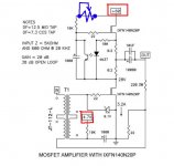
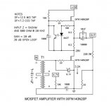
Breaking down into 3 areas, input section, output section and current source.
Input: uses a 1 to 1 transformer, no gain. Provides good isolation for noise on input.
Output: uses very heavy duty mosfet to handle the power and is set with Schade feedback to get the triode curves. It's also single ended where one mosfet handles 100% of the cycle.
Current Source: uses another heavy duty mosfet and clever iso-coupler to set the constant current source (ccs)
So no matter what happens with the voltage, the current delivery is constant.
A 50w build will be large so mono blocks are recommended.
I'm sure I'm missing something, so someone else please correct and fill in the gaps.
In someway, the ACA (amp camp amp has some characteristics of this amp. The SE 50w has feedback that give the mosfet triode characteristics, so it's special that way.
There are other SE Schade feedback amp examples here but none this simple. If you go to firstwatt.com and passdiy.com most of this is broken down in the articles sections.
Breaking down into 3 areas, input section, output section and current source.
Input: uses a 1 to 1 transformer, no gain. Provides good isolation for noise on input.
Output: uses very heavy duty mosfet to handle the power and is set with Schade feedback to get the triode curves. It's also single ended where one mosfet handles 100% of the cycle.
Current Source: uses another heavy duty mosfet and clever iso-coupler to set the constant current source (ccs)
So no matter what happens with the voltage, the current delivery is constant.
A 50w build will be large so mono blocks are recommended.
I'm sure I'm missing something, so someone else please correct and fill in the gaps.
Last edited:
Breaking down into 3 areas, input section, output section and current source.
Input: uses a 1 to 1 transformer, no gain. Provides good isolation for noise on input.
Output: uses very heavy duty mosfet to handle the power and is set with Schade feedback to get the triode curves. It's also single ended where one mosfet handles 100% of the cycle.
Current Source: uses another heavy duty mosfet and clever iso-coupler to set the constant current source (ccs)
So no matter what happens with the voltage, the current delivery is constant.
Isn't the input transformer part of the Schade feedback arrangement?
Isn't the input transformer part of the Schade feedback arrangement?
Yes it is and it also increases the input impedance so that a regular preamp can drive the amp. See 37m 50m mark of the video.
https://youtu.be/wa_k0abLpAU
If my simulation is right it looks like the bias adjustment will be pretty touchy with a single 5k pot. Might have to use both a coarse and a fine adjustment. I used this circuit with the baf2015 circuit and in simulation the 1000u cap that is connected to ground took care of all the ripple. And wow! Won't it take about a whole minute to reach the peak bias voltage because of the 10k ohm and 1000u values.
Attachments

Please look here....
No easy task, some people tried it already, I would only do it with the servo ZM made!
http://www.diyaudio.com/forums/pass-labs/280950-baf-2015-coverage-65.html#post4588152
No easy task, some people tried it already, I would only do it with the servo ZM made!
http://www.diyaudio.com/forums/pass-labs/280950-baf-2015-coverage-65.html#post4588152
- Home
- Amplifiers
- Pass Labs
- 50w Single-Ended BAF2015 Schade Enabled