Pin 6 goes nowhere, correct?
Do opto-coupler transistor work without base connected ?
You can control optocoupler either by LED or by transistor base. In this cas it is controled by LED so base is not used.
You can control optocoupler either by LED or by transistor base. In this cas it is controled by LED so base is not used.
Yes confirmed M2 amp use opto-couplers that way : base no connected.
That i see on his pcb's. Thanks for response
Great !
Postman bring me today two 100kuF/80V is for project's with higher voltages.
Caps are large like ~ bench lab psu. Perfect for Schade 50W and Tokin sit's test's.
I pray Mother Earth and Father Cosmos all will be happens.

Postman bring me today two 100kuF/80V is for project's with higher voltages.
Caps are large like ~ bench lab psu. Perfect for Schade 50W and Tokin sit's test's.
I pray Mother Earth and Father Cosmos all will be happens.
Attachments

Thinking about psu and need find nice candidate for Schade 50.
What is transformer secondary voltage to get +60V after filtering ?
Maybe schematic example available ?
Any councils : passive, regulated or other psu ?
Thanks in advance for your answer
What is transformer secondary voltage to get +60V after filtering ?
Maybe schematic example available ?
Any councils : passive, regulated or other psu ?
Thanks in advance for your answer
I'm using a 60v 900va frame transformer for each monoblock.
It's in choke input, with two stages of choke/cap and with a cheat cap of 1uf I'm getting 60v at the load resistor on test.
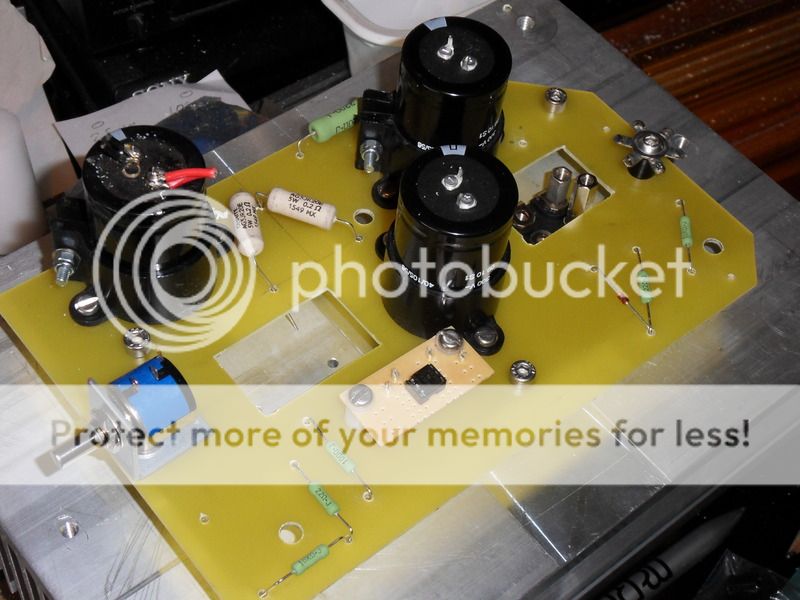
The first breadboard amp (of two) is under construction, the circuit board (FR-4 with turret tags) is finished and populated.
Just got to finalise wiring up the input transformer (Danbury transformers interstage) and sorting out the in-out sockets, the on-off switch and fitting the bias transformer and module.
One point to make, the mosfet grid stopper resistors should be fitted as close as possible to the mosfet. I was reminded about that by a friend.The positioning of them on my board (as per picture) was changed before everything was soldered up.
PS I used Duncans PSU designer to model the power supply and providing you input accurate data the results are spot on.
The circuit board work in progress.
It's in choke input, with two stages of choke/cap and with a cheat cap of 1uf I'm getting 60v at the load resistor on test.
The first breadboard amp (of two) is under construction, the circuit board (FR-4 with turret tags) is finished and populated.
Just got to finalise wiring up the input transformer (Danbury transformers interstage) and sorting out the in-out sockets, the on-off switch and fitting the bias transformer and module.
One point to make, the mosfet grid stopper resistors should be fitted as close as possible to the mosfet. I was reminded about that by a friend.The positioning of them on my board (as per picture) was changed before everything was soldered up.
PS I used Duncans PSU designer to model the power supply and providing you input accurate data the results are spot on.
The circuit board work in progress.

Last edited:
I need another amp like a hole in the head but I was there at the presentation so I am thinking about building. It is a hobby after all.
I have a question about the IXFK 120N20P. Is the tab insulated or is it the drain. The datasheet has confused me.
ray
ray
I have a question about the IXFK 120N20P. Is the tab insulated or is it the drain. The datasheet has confused me.
ray
ray
Hockey puck's IXFN140N20P stock at Mouser dry bit more today


http://www.mouser.fr/ProductDetail/IXYS/IXFN140N20P/?qs=t7yjd2JO/gTEsrKBTipgAg==
Kindest regards
http://www.mouser.fr/ProductDetail/IXYS/IXFN140N20P/?qs=t7yjd2JO/gTEsrKBTipgAg==
Kindest regards
Attachments


....and fitting the bias transformer and module.
What your 4.7 V bias circuit choice could you please write more about ?
Mr. Pass solution ?
Best regards 😀
Attachments

I normally build valve (tube) amps, and I had a pair of DIY audio filament modules in my spares box, and also a pair of 6v toroids, so I am using them.
If I was starting from nothing I'm not sure how I would proceed.
I'm in the process of testing my first prototype, but the heatsink is getting to hot and affecting the voltage readings. A household fan is helping to keep it cool at the moment.😱
If I was starting from nothing I'm not sure how I would proceed.
I'm in the process of testing my first prototype, but the heatsink is getting to hot and affecting the voltage readings. A household fan is helping to keep it cool at the moment.😱
Oh yes tube filament circuits with modifications can do it.
My start is from potentialy every bias circuit and his psu possible position.
I get by chance some big heatsinks to experiment but it's not that fearless " car style " class A build by great Diyer 😀
My start is from potentialy every bias circuit and his psu possible position.
I get by chance some big heatsinks to experiment but it's not that fearless " car style " class A build by great Diyer 😀
Attachments


The heatsinks I am using came from a computer UPS power supply and I thought they would keep the two mosfets cool enough without any fans.
It seems the 10K resistor and 1000uf cap on the bias supply make it very slow to react to changes, so bear that in mind.
Those heatsinks of yours look good, any spares ?
It seems the 10K resistor and 1000uf cap on the bias supply make it very slow to react to changes, so bear that in mind.
Those heatsinks of yours look good, any spares ?
Those heatsinks of yours look good, any spares ?
Thanks Pre65 🙂
This huge heatsinks was from my city local metal company recycling.
Not for sale on order and is unknow model reference.
Maybe something from England Birmingham few big ones like this :
Heatsinks: 7000 series - 7200HS | BAL Group Ltd
Heatsinks: 5000 Series - 5460HS | BAL Group Ltd
Attachments


Share my joy of received IXYS today
They are example of spectacular quality made semi's.
Vive le Papa Diy !
They are example of spectacular quality made semi's.
Vive le Papa Diy !
Attachments


French distributor Selectronic close all shops and stop deals on line
....i regret was good source for 500 VA r-cores. Some times with promotions : final price less -20 % or 40 %.
I do try find ~ 600 ~800 VA at resonable cost probably Toroidy or Antek 🙂
....i regret was good source for 500 VA r-cores. Some times with promotions : final price less -20 % or 40 %.
I do try find ~ 600 ~800 VA at resonable cost probably Toroidy or Antek 🙂
- Home
- Amplifiers
- Pass Labs
- 50w Single-Ended BAF2015 Schade Enabled