2sk180
Hello,
I know Ben was successful in building this amp using THF-51S. I have
a few 2SK180 stashed away somewhere (if I can find them") ).
).
My first look at what info I can find on the 2sk180 doesn't seem to raise any
red flags. I'm wondering what your thoughts are on using the 2sk180
in this amp?
Thanks,
Dennis
Hello,
I know Ben was successful in building this amp using THF-51S. I have
a few 2SK180 stashed away somewhere (if I can find them
). My first look at what info I can find on the 2sk180 doesn't seem to raise any
red flags. I'm wondering what your thoughts are on using the 2sk180
in this amp?
Thanks,
Dennis
Hi Dennis,
Michael Rothacher built a L'Amp with 2SK180 several years ago:
L’Amp 2SK180 Video | AudioMaker
Curves:
YouTube
Looks possible. I think others have successfully used the 2SK180 in amplifiers too.
Ben
I just realized that the 2SK180 is a 300W device whereas the THF-51S is 400W. Maybe pushing it at 3.2A and 28V?

View attachment 2SK180_YoshinoInternational.pdf
Michael Rothacher built a L'Amp with 2SK180 several years ago:
L’Amp 2SK180 Video | AudioMaker
Curves:
YouTube
Looks possible. I think others have successfully used the 2SK180 in amplifiers too.
Ben
I just realized that the 2SK180 is a 300W device whereas the THF-51S is 400W. Maybe pushing it at 3.2A and 28V?
View attachment 2SK180_YoshinoInternational.pdf
Last edited:
...Which version...
Thought I'd start with the 50 Watt VFET using THF51, then add a BA1 FE to morph it into another J2; then do the same again with some SJEP120R100
I forgot, I also have some UJ3N065080K3S I'd like to try
Last edited:
Thought I'd start with the 50 Watt VFET using THF51, then add a BA1 FE to morph it into another J2; then do the same again with some SJEP120R100
I forgot, I also have some UJ3N065080K3S I'd like to try
VGS on UJ3N065080K3S is quite high but will definitely be interested to hear your results as I have 'a few' of these as well!
Recently I was asked by two diyAudio members about my build. It seemed the lack of success of some members' builds had some wondering how I built my amps and got them working. I am a self taught diyer who has learned a lot from reading the forums, and I am still learning from reading the writing of others. So I am trying to include information that will help those with less experience, as others have helped me.
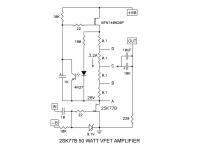
My build did not deviate much from Nelson's schematic. It actually worked as is except for my substitution of the THF-51S in place of the 2SK77B, which is of course unobtanium for most of us. The current source did output 3.5A instead of 3.2A indicated on the schematic. It is interesting that Nelson did mention 3.5A in his BAF2015 video. I changed the 10K resistor between the drain and gate of the IXFN to 16K which dropped the current to about 3.25A.
The only other deviation is that my CLC power supply provided 62.5V instead of 60V. That was because my choice of transformer and choke in the CLC filtering gave me that number. In my case I chose a 50V 600VA Antek transformer for each monoblock and the final VDC ended up being 1.25x50V. However it did work as built in accordance with the schematic, even at 62.5V and 3.5A.
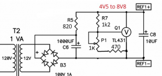
For my bias supply, I modified Zen Mod's circuit (50w Single-Ended BAF2015 Schade Enabled post#508) to suit the Vgs of my THF-51Ss.
I had purchased four THF-51Ss when I was planning my SissySit build, and I used Zen Mod's test circuit (SissySIT post#81) to determine their Vgs at 24V and 1.8A. The THF-51Ss that I had left for my BAF amps had Vgs of about 3.5 and 3.8V. Note that in the BAF amp, the output device operates at 28V and 3.2A. In my amps, that meant a decrease of nearly 0.5V in Vgs from those measured at 24V and 1.8A. I modified the Zen Mod bias circuit by replacing the 1K pot with a 5K pot. That changed to output voltage range to 3V0 to 8V8. If you find that you need a bias supply that goes lower than 3V, I suggest replacing the TL431 with the TLVH431. The TLVH431 has Vref=1.24V whereas the TL431 has Vref=2.5V. This changes the output voltage range to between 1.5V and 4.4V. Another possible solution would be to use a resistor voltage divider to drop the voltage of the TL431 circuit.
In my build, I built and tested in stages. I made sure that each stage was working properly before adding the next stage. I always do this for all my builds.
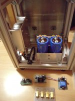
I built my power supply first and tested it when completed. I used a dim bulb tester for initial power up. Note if powered up without a load connected, the power supply capacitors will stay charge after the AC power is off. Always provide a bleed resistor in your power supply and check the voltage across the capacitors before touching. I also put a LED in my power supply so I have visual warning of charged capacitors.
Most of you know Ohm's Law and can figure out bleed resistors, but for the ones that need a bit of assistance:
Ohm's Law is E=IR where E=electromotive force in Volt, I is current in Ampere, and R is resistance in Ohm
To calculate a bleed resistor, first choose a bleed current, say 10mA (0.010A). The choice is a compromise between speed of draining the capacitors, power rating of bleed resistor, and permanent current demand on the power supply. Using Ohm's Law:
E=IR, or R=E/I = 60V/0.010A = 6000 Ohm, Power = EI = IR x I = Isquared R = 0.010A squared x 6000 Ohm = 0.60W
So the choice of 10mA bleed current at 60V gives 6000 Ohm (or closest available) resistor with 0.60W heat dissipation. For practical purposes choose 2W or higher to keep the resistor temperature low, and mount the resistor with a bit a clearance to the PC board. Note that with lots of capacitance in the power supply, it may the bleed resistor in an unloaded supply a while to drain the capacitors.
After the initial power up test for short, I usually test the supply with resistor dummy load. With this amp, I did not test to full current output. I strung some 10W power resistors together and briefly tested the supply at 0.5A if I remember correctly. I felt that with a simple CLC (or CRC) supply, provided that the components have been sized for the correct voltage and current, testing at a lower current demand is enough to satisfy myself that the supply is operating correctly. Sizing of the resistor dummy load is the same procedure as sizing the bleed resistor, for those that need assistance.
For those that are using a lab supply, I have read of diyers that have had issues with current limiting. I don't have a lab supply so I do not have any experience with them, but perhaps a test of the lab supply at full current demand with a dummy load may be something that can be done so that you can be confident that it can deliver the current.
With the power supply done, I built and then tested the IXFN current source. The current source (everything from the 60V supply to but not including the 2SK77B on the schematic) was connected to the power supply, and an 8 Ohm test load was connected to the end of the current source (point A on the schematic). My 8 Ohm load was two 50W 4 Ohm metal clad power resistors mounted on a heat sink (resistor power dissipation = 3.2A x 3.2A x 8 Ohm = 82W). I initially powered up with a dim bulb tester to check for shorts. With the 60V 3.2A power demand, I used a 250W bulb in the tester. With that done and no short detected, I powered up at full power and measured the voltage across the test load. The expected voltage drop was 3.2A x 8 Ohm = 25.6V. I was in that neighbourhood. I believe that I actually got 26.7V and as my test load measured 8.2 Ohm, the current source was outputting about 3.25A - close enough.
This is also a good time to test the amplifier heatsink. Instead of mounting the test load on a separate heat sink, mount the test load on the amplifier heat sink along with the IXFN device and check the heat sink temperature.
I then built the rest of the amplifier circuit and the bias supply circuit. I tested the bias supply circuit separately with a dummy resistor load (I think I sized the load for 2 or 3mA at 3V). I also made sure that I set the bias supply at maximum output voltage before I connected it to the THF gate.
For the first power up of the complete amplifier, again I used the dim bulb tester. I also had a meter on the THF drain and source (ground), a meter across one of the 0.1 Ohm resistors at the THF drain to monitor current, and one meter to monitor the PS voltage. With no short detected, I powered up with full AC power, and adjusted the bias supply pot, watching as the voltage across the THF dropped to 29V. Initially with the bias at -8.8V, the THF was off and there was no current flowing. I chose 29V instead of the 28V shown on the schematic as my V+ was 62.5V, not 60V.
This was route I took in building my amps. The most important point is that I built and tested in stages. Start at the beginning and test the power supply, then proceed stage by stage. Double and triple check before powering up, and don't rush.
And have fun.
PS: See posts #857 50w Single-Ended BAF2015 Schade Enabled and #905 50w Single-Ended BAF2015 Schade Enabled for pictures and more info.
My build did not deviate much from Nelson's schematic. It actually worked as is except for my substitution of the THF-51S in place of the 2SK77B, which is of course unobtanium for most of us. The current source did output 3.5A instead of 3.2A indicated on the schematic. It is interesting that Nelson did mention 3.5A in his BAF2015 video. I changed the 10K resistor between the drain and gate of the IXFN to 16K which dropped the current to about 3.25A.
The only other deviation is that my CLC power supply provided 62.5V instead of 60V. That was because my choice of transformer and choke in the CLC filtering gave me that number. In my case I chose a 50V 600VA Antek transformer for each monoblock and the final VDC ended up being 1.25x50V. However it did work as built in accordance with the schematic, even at 62.5V and 3.5A.
For my bias supply, I modified Zen Mod's circuit (50w Single-Ended BAF2015 Schade Enabled post#508) to suit the Vgs of my THF-51Ss.
I had purchased four THF-51Ss when I was planning my SissySit build, and I used Zen Mod's test circuit (SissySIT post#81) to determine their Vgs at 24V and 1.8A. The THF-51Ss that I had left for my BAF amps had Vgs of about 3.5 and 3.8V. Note that in the BAF amp, the output device operates at 28V and 3.2A. In my amps, that meant a decrease of nearly 0.5V in Vgs from those measured at 24V and 1.8A. I modified the Zen Mod bias circuit by replacing the 1K pot with a 5K pot. That changed to output voltage range to 3V0 to 8V8. If you find that you need a bias supply that goes lower than 3V, I suggest replacing the TL431 with the TLVH431. The TLVH431 has Vref=1.24V whereas the TL431 has Vref=2.5V. This changes the output voltage range to between 1.5V and 4.4V. Another possible solution would be to use a resistor voltage divider to drop the voltage of the TL431 circuit.
In my build, I built and tested in stages. I made sure that each stage was working properly before adding the next stage. I always do this for all my builds.
I built my power supply first and tested it when completed. I used a dim bulb tester for initial power up. Note if powered up without a load connected, the power supply capacitors will stay charge after the AC power is off. Always provide a bleed resistor in your power supply and check the voltage across the capacitors before touching. I also put a LED in my power supply so I have visual warning of charged capacitors.
Most of you know Ohm's Law and can figure out bleed resistors, but for the ones that need a bit of assistance:
Ohm's Law is E=IR where E=electromotive force in Volt, I is current in Ampere, and R is resistance in Ohm
To calculate a bleed resistor, first choose a bleed current, say 10mA (0.010A). The choice is a compromise between speed of draining the capacitors, power rating of bleed resistor, and permanent current demand on the power supply. Using Ohm's Law:
E=IR, or R=E/I = 60V/0.010A = 6000 Ohm, Power = EI = IR x I = Isquared R = 0.010A squared x 6000 Ohm = 0.60W
So the choice of 10mA bleed current at 60V gives 6000 Ohm (or closest available) resistor with 0.60W heat dissipation. For practical purposes choose 2W or higher to keep the resistor temperature low, and mount the resistor with a bit a clearance to the PC board. Note that with lots of capacitance in the power supply, it may the bleed resistor in an unloaded supply a while to drain the capacitors.
After the initial power up test for short, I usually test the supply with resistor dummy load. With this amp, I did not test to full current output. I strung some 10W power resistors together and briefly tested the supply at 0.5A if I remember correctly. I felt that with a simple CLC (or CRC) supply, provided that the components have been sized for the correct voltage and current, testing at a lower current demand is enough to satisfy myself that the supply is operating correctly. Sizing of the resistor dummy load is the same procedure as sizing the bleed resistor, for those that need assistance.
For those that are using a lab supply, I have read of diyers that have had issues with current limiting. I don't have a lab supply so I do not have any experience with them, but perhaps a test of the lab supply at full current demand with a dummy load may be something that can be done so that you can be confident that it can deliver the current.
With the power supply done, I built and then tested the IXFN current source. The current source (everything from the 60V supply to but not including the 2SK77B on the schematic) was connected to the power supply, and an 8 Ohm test load was connected to the end of the current source (point A on the schematic). My 8 Ohm load was two 50W 4 Ohm metal clad power resistors mounted on a heat sink (resistor power dissipation = 3.2A x 3.2A x 8 Ohm = 82W). I initially powered up with a dim bulb tester to check for shorts. With the 60V 3.2A power demand, I used a 250W bulb in the tester. With that done and no short detected, I powered up at full power and measured the voltage across the test load. The expected voltage drop was 3.2A x 8 Ohm = 25.6V. I was in that neighbourhood. I believe that I actually got 26.7V and as my test load measured 8.2 Ohm, the current source was outputting about 3.25A - close enough.
This is also a good time to test the amplifier heatsink. Instead of mounting the test load on a separate heat sink, mount the test load on the amplifier heat sink along with the IXFN device and check the heat sink temperature.
I then built the rest of the amplifier circuit and the bias supply circuit. I tested the bias supply circuit separately with a dummy resistor load (I think I sized the load for 2 or 3mA at 3V). I also made sure that I set the bias supply at maximum output voltage before I connected it to the THF gate.
For the first power up of the complete amplifier, again I used the dim bulb tester. I also had a meter on the THF drain and source (ground), a meter across one of the 0.1 Ohm resistors at the THF drain to monitor current, and one meter to monitor the PS voltage. With no short detected, I powered up with full AC power, and adjusted the bias supply pot, watching as the voltage across the THF dropped to 29V. Initially with the bias at -8.8V, the THF was off and there was no current flowing. I chose 29V instead of the 28V shown on the schematic as my V+ was 62.5V, not 60V.
This was route I took in building my amps. The most important point is that I built and tested in stages. Start at the beginning and test the power supply, then proceed stage by stage. Double and triple check before powering up, and don't rush.
And have fun.
PS: See posts #857 50w Single-Ended BAF2015 Schade Enabled and #905 50w Single-Ended BAF2015 Schade Enabled for pictures and more info.
Attachments

Recently I was asked by two diyAudio members about my build. .....
Nicely done , Ben , proper procedure

I'm still waiting for pcbs ( chained at Customs) for Singing Bush (post #100) and it's iterations ......
I will try...this amp
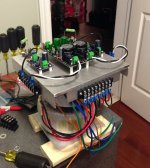
I am at this stage of my build. I hope it will come alive without a disaster.
I build the version with the IXYS - hockeypucks. Poor mans iteration...
Hope to get the PSU done next few days. Still a lot of work waiting.
Thanks to BenMah for your guidance. A big help.
Greets
Dirk
I am at this stage of my build. I hope it will come alive without a disaster.
I build the version with the IXYS - hockeypucks. Poor mans iteration...
Hope to get the PSU done next few days. Still a lot of work waiting.
Thanks to BenMah for your guidance. A big help.
Greets
Dirk
Attachments
- Home
- Amplifiers
- Pass Labs
- 50w Single-Ended BAF2015 Schade Enabled