Nelson,
So then if one were to consider an XA100.5 type output stage with 10 pairs of complementary followers per side built with say; 150W P and N channel MOSFET's with .47 ohm 3 watt source degeneration resistors, and lets say 12 1K 3W resistors on each side connected between the output node and V-, would one then have an output stage that sounded close to a factory unit - say in the same sense as the original XA and GR's original AX?
Graeme
hello Mr. Pass,
do not really come to a result... :-(
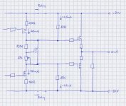
I have done a small sketch.
Are the two resistors all what I need?
I conceive this approach in the following way:
When the front end is turned off, there is only a very small current - say 2,5mA - running through the voltage bias circuit. That lowers the Vgs and with the voltage divider the Vds of the bias-MOSFET.
Is that right?
You use a lot more parts for it (mean to see 2x resistors (3W), 5x resistors (1/4W), 1x trimmer, 2x elcaps and an unknown part (cap or another transistor)).
I have done something wrong!?????
Other problem is that I come to no conclusion what you mean with "the equivalent of 5K to ground"?
It looks to me like a voltage divider and so a voltage of 10V above ground (with supplyrails at 30V) (over the 5k resistor: 10V above gnd or over the 10k resistor: 20V below the supply rails) ..............??????????
Please, hold my brain on temperature!")
Dirk
do not really come to a result... :-(
I have done a small sketch.
Are the two resistors all what I need?
I conceive this approach in the following way:
When the front end is turned off, there is only a very small current - say 2,5mA - running through the voltage bias circuit. That lowers the Vgs and with the voltage divider the Vds of the bias-MOSFET.
Is that right?
You use a lot more parts for it (mean to see 2x resistors (3W), 5x resistors (1/4W), 1x trimmer, 2x elcaps and an unknown part (cap or another transistor)).
I have done something wrong!?????
Other problem is that I come to no conclusion what you mean with "the equivalent of 5K to ground"?
It looks to me like a voltage divider and so a voltage of 10V above ground (with supplyrails at 30V) (over the 5k resistor: 10V above gnd or over the 10k resistor: 20V below the supply rails) ..............??????????
Please, hold my brain on temperature!
Dirk
Attachments
gl said:So then if one were to consider an XA100.5 type output stage with 10 pairs of complementary followers per side built with say; 150W P and N channel MOSFET's with .47 ohm 3 watt source degeneration resistors, and lets say 12 1K 3W resistors on each side connected between the output node and V-, would one then have an output stage that sounded close to a factory unit
In the sense that it would share the general topology, yes.
In the sense that we have built several examples of this
circuit which don't sound the same, no.
Nelson Pass said:Yes, 40 devices / ch
That is a lot of devices! Is the outputstage perhaps run open loop? Any resemblance to the F4?
gl said:
So then if one were to consider an XA100.5 type output stage with 10 pairs of complementary followers per side built with say; 150W P and N channel MOSFET's with .47 ohm 3 watt source degeneration resistors, and lets say 12 1K 3W resistors on each side connected between the output node and V-, would one then have an output stage that sounded close to a factory unit - say in the same sense as the original XA and GR's original AX?
Graeme,
How did you arrive at 12 x 1K 3W resistors? This would be an equivalent resistance of around 83R per side and hence a SE bias of 0.36A per side. Perfectly reasonable but I am interested in how you arrived at this value of SE bias.
Ian.
noisefree said:I have done a small sketch.
Are the two resistors all what I need?
I conceive this approach in the following way:
When the front end is turned off, there is only a very small current - say 2,5mA - running through the voltage bias circuit. That lowers the Vgs and with the voltage divider the Vds of the bias-MOSFET.
Is that right?
You use a lot more parts for it (mean to see 2x resistors (3W), 5x resistors (1/4W), 1x trimmer, 2x elcaps and an unknown part (cap or another transistor)).
I have done something wrong!?????
Other problem is that I come to no conclusion what you mean with "the equivalent of 5K to ground"?
It looks to me like a voltage divider and so a voltage of 10V above ground (with supplyrails at 30V) (over the 5k resistor: 10V above gnd or over the 10k resistor: 20V below the supply rails) ..............??????????
Dirk,
I can help with the last question since that is the easy one. The 5K to ground refers to small signal model where the power rails are considered to be both tied to ground (the PS having a low internal impedance). In this case the two 10K resistors appear in parallel to ground as far as the signal is concerned, i.e. the equivalent of a 5K resistor to ground.
I'm not convinced by your reasoning with regard to the bias circuit (Vgs multiplier) as I suspect that it will generate pretty much the same voltage with 2.5mA as it will with 20mA. The resistors to the power rails look fine to me though and will also help to control the open loop gain of the amplifier.
I've no idea what Nelson uses the 3W resistors for but I'm sure it must be significant.
Ian.
Hi Ian,
I'm just deciphering the NP breadcrumbs and having fun in the process. Please don't think that there is any great intellectual epiphany going on. Here's the reasoning (just for fun):
First the twelve: There are 40 output transistors requiring one source degeneration resistor each. The Japanese brochure with the photo of the XA100.5 innards shows 64 3W Panasonic resistors on the output boards. That means 64 - 40 = 24 resistors left over or 12 per side for a SuSy amp. There, that's where the 12 comes from.
Right, now for the 1K: The rail voltages on the output section are probably going to be 25V to 32V. The resistors are 3W so the dissipation on each resistor will be roughly 1W or a bit less. This provides enough information to start calculating the value. I forget what the exact value was but the important thing is the ballpark. Once you're in the the ballpark you pick something close that you have on hand. In this case the ballpark came out to within throwing distance of 1K. Coincidently this is the value of resistor Nelson had used to create the compound output to ground load resistor on the old XA160/XA200. He loves to use the same parts over and over, and he sticks to limited numbers of resistor and capacitor values.
It seemed to pass the smell test IMHO.
Regards,
Graeme
gl said:He loves to use the same parts over and over, and he sticks to limited numbers of resistor and capacitor values.

I was replying to Dirk (noisefree) who I believe was talking about 2 3W resistors he thinks are related to the AX100.5 Vgs multiplier on the UGS5 board as seen from a photo. Of course I could be wrong... Dirk?Nelson Pass said:What 3 watt values are those, and what version amplifier
are you talking about?
Ian.
gl said:I'm just deciphering the NP breadcrumbs and having fun in the process. Please don't think that there is any great intellectual epiphany going on. Here's the reasoning (just for fun):
Graeme,
I like your reasoning and although I've no idea how close to reality it is, I agree with it passing the smell test
Whilst on the subject of deciphering the various NP breadcrumbs, I have a few questions I am pondering too - maybe you can help?
1. Why 40 output devices? This seems overkill and more importantly makes it hard for the front end to drive the capacitance. Also a problem for device matching. Obviously there is a reason as Nelson doesn't throw in unneccessary parts. Come to think of it, I have been assuming these are IRF240/9240 but do we know this?
2. How much current do we need from the front end to drive 20 output devices (per side)? From an earlier breadcrumb, NP said that the VAS stage provides just x5 current gain which means around 25mA if the diff pair is running at 5mA per side. Is this sufficient for so many devices? Can't see how we can get much more out of the front end unless V type FETs are used with higher Idsss.
3. I'm also pondering Dirk's comments about the likely open loop gain of the AX100.5 which would be lower than I expected if he is right. Could be that this is important and hence loading the VAS stage with the equivalent 5K does more than just cope with any standby circuit requirements.
Any and all help welcomed, speculative or otherwise...
Ian.
Hi Ian,
Well, for starters I'm glad I didn't upset Nelson with my comments on parts usage. As you know I'm slowly putting together my own version of an AX.5 - again just for the fun of it. A 2SJ109 front end for my AX100's is first - then this. About a years worth of work I figure. So you'll probably beat me to it.
Here's my speculative two cents worth regarding your questions:
1) Regarding the output transistors: Nelson has been very coy here, saying only that he is using new output devices (for him) and that there are 40 of them in a complementary follower arrangement. Some of his recent posts refer to these parts using MOSFET terminology. So I think they're MOSFET's rather than BJT's. The photo shows that the package is a TO-247/TO-3P. In short I don't believe that these are vertical MOSFET's. I browsed the offerings a while back and was distressed to find hard it was to pick complementary parts that had low input capacitance, that weren't being obsoleted for RoHS or other reasons, and which weren't hopelessly optimized for switching applications. Plus all the major lines have been bought and sold a time or two in recent years. Absolute chaos. In my minds eye I imagined Nelson looking at this, seeing himself having to go through the whole IRF244 again and saying "Let's do this differently this time".
That leaves two likely choices: the 2SK1530 et al. and the 2SK1058 et al. My guess is the latter. There has been a great discussion over on Solid State recently on the topic of verticals vs. laterals. The 2SK1058 has roughly half the input capacitance of the IRFP240 for example. So 40 devices instead of the old 20-24 in the XA100 now makes sense. The transconductance of laterals is much lower than verticals so you need to parallel more of them. Again that helps explain how we get to 40. And finally if you look at the XA100.5 photo you see that the Vgs/Vbe multiplier in the bias circuit is a TO-92 or some such small package. We know that the current through this part is 25ma. If the output transistors are verticals then there will be about 10 volts across it. IMHO that's too much power being dissipated. If the outputs are laterals then we would have only 3 to 4 volts here. Quite reasonable.
2) Yes this is enough current IMO.
3) The output side of the current mirror is a current source. The two 10K resistors are there to provide the load that changes this to a voltage source. Are they required? I don't know. VAS load resistors are a debated topic. This part of the circuit appears to have been complicated by the necessity of having a standby feature. I'm not planning on implementing standby but I will use the 10K resistors. I feel pretty certain that the voltage gain in the UGS5 all comes from the input JFET's and is the same as for the UGS3 and 4 - about 40dB open loop.
These are just my personal views and mental doodles.
Regards,
Graeme
Graeme,
Very thought-provoking - thanks for your sharing your musings.
I see that assumptions are dangerous things and now I will have to start thinking more carefully about component choice. You must have very good eyesight to spot that the packages are TO-3P. No doubt the 40 lateral MOSFETS (if that is what they are) will sound different to 20 verticals and that may also be the reason why NP went this route (if indeed he did). I'll read up on the thread you mention.
Given that you clearly have a better eye than I (horrible pun), perhaps I could also ask you about some other curiosities I and others have spotted from the UGS5 photo. For instance the VAS devices are clearly on heatsinks (which itself probably tells us something about the current they are operated at) and look to be more like IRF610 or similar rather than the older ZVN3310 or similar. What are your thoughts here? Come to that, even the cascodes (although this could be another faulty assumption on my part) appear to be larger than normal parts. I think they might be TO-126 packages as opposed to the smaller ZTX pieces. Might this suggest higher current and/or higher voltage on the front end?
Sorry, lots of questions and I'm not offering much in return. I'll see if I can't remedy this over the next few weeks.
BTW, I'm fairly certain that resistive loading is not required for the VAS to work properly but may well be helpful in controlling the open-loop gain. Validation will probably have to wait until I have something built to experiment with. I am not planning on any kind of standby circuit so I don't need this aspect.
Ian.
- Home
- Amplifiers
- Pass Labs
- Aleph-X builder's thread.