Yep! Duchtig, dygtig, Its the same. Let them cook for nowjacco vermeulen said:Duchtig ?
 Especially ZM needs a little cooking.....
steenoe said:Yep! Duchtig, dygtig, Its the same. Let them cook for now

Hi Steen,
thanks for your answer.
OK, the questions were to direct and indiscreet.
I hope that Mr Pass isn't displeased about it.
I have read a lot in this forum and have all the service-manuals
No problem.....enough helpfully details to find.
About my questions:
Number 2 is about something new and I've understood not to ask for such things.
But number 1 is an interesting old but for this forum new detail which maybe can be answered by the three or more AX-experts out there. The concept is five(?) years old....
Number3: I asked that only for my understanding. I don't want to copy it or doing it in the same way.
My wish is to create something like the XA.5.
At the moment I have not enough time, but have started a layout for the output-boards with CCSs which can be used for one bridgeside or the whole amplifier......ohh and I have to find a cheap boardmanufacturer...
....it should end a bit professional!!!......I hope........
Greetings
Dirk
noisefree said:1. XA160 :
What is the resistor on the Aleph-CS for which is attached from collector to emitter on the ZTX450 transistor? Current limiting on the positive half or DC-offset stabilisation?
2. XA60.5/XA100.5 :
Does each bridge side uses FOUR parallel N-ch. mosfets as CCS?
(+ eight N-ch. and P-ch complementary pairs?) What are these power-resistors for?
3. XA350.5 :
The SE-CCS is made of a power-pnp-transistor and a high-power-resistor (20W/ 50W with heat sinking) attached between output and emitter. For this kind of CCS you need a reference voltage between base and output for turning it on. Which value has this voltage and how can I generate it?
1) The resistor trims the bias current, as the ZTX450 is used
to set the current source DC value
2) No, each side uses 20 parallel sets of complementary
follwowers. The resistors are for dissipation of the single-ended
bias.
3) Try a simple switch.
Thanks a lot Mr. Pass for answering my questions!!!
1) When I have understood it in the right way then there are more places where this can be done and this is one of it!?
I have to think about it.....
2) OK!!!!! Same kind of SE-bias as in the X.5
3) Then it is a resistor biasing. But why switching it on and off?
Is it because off to much DC at the output when the amplifier is turned on or off? The SE-resistor-bias comes a bit later in action after the caps are loaded and the PP-bias is more stable!?
Greetings
Dirk
Oh, I've forgotten a possibility for number 3)
Because of the stand-by-circuit! When the front end is powered down and there is no bias current running through the PP-devices you have to turn off the SE-bias or you will see the supply voltage at the output!
Right....?
But I can't see a switching transistor in the XA.5 amps for doing that. There are only four cables to the output boards (without the smaller driving cables): +/- supply voltage and two cables for the outputs which can be taken in parallel or used seperat (each for one bridge half).
I'm thinking..........!!!???
.....other kind of stand-by-circuit....?
Dirk
Oh that's really exciting..........
noisefree said:Oh that's really exciting..........
Not really. You can switch the SE bias on and off as you please.
Since there is a resistive reference at the output of the
front end, it does not drag the output to the rails.
Äääähhhhhh............
hello and many, many thanks again!!!
hope to understand you right...
I try to resume:
When using resitor(s) for the (parallel) SE bias you have to do something against the negativ output DC in stand-by mode and/or turning amp on / off.
This can be done
- with a switch for the bias resistor to turn it off
- or (perhaps a bit more elegant) in the front end circuitry. It must be something that holds the output at zero and leaving the N-bank in a small conducting state - the SE bias will be in action during the stand by mode.
You call it resistive reference at the front end output.
.......I'm a bit confused what this can be???
Only a resitor which connects the gates to ground?
Hmmmm....can't see the light....I've to reconsider.....
Perhaps yet another question to stay on the right way: Is the voltage bias cuircuit similar to X5 or is it more like a F4 (with the driver output pins connected together and caps for coupling)?
.......................................................?
best regards
Dirk
sorry, sorry, sorry.....me again.....
I've forgotten the most important questions:
When I don't need a stand-by circuit, is it possible to realize an PP-XA (with resistor SE-bias) with something very similar to the UGS4, but with more driving current for 10 parallel output devices and a voltage bias circuit like a X5 (or other X)uses, or will that destroy my loved Tannoys when turning on/off this amp?
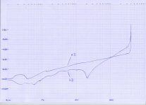
I've drawn down the k2 und k3 components of a X-amp (have seen that in a magazin). Could you explain what happen with k3 @ 20W.
Why is it so low only for a short periode of outputpower?
It has something to do with the SE-bias, but I don't know what?
I'm very ashamed asking you so much.....
I hope not to dance on your nerves.....
Dirk
I've forgotten the most important questions:
When I don't need a stand-by circuit, is it possible to realize an PP-XA (with resistor SE-bias) with something very similar to the UGS4, but with more driving current for 10 parallel output devices and a voltage bias circuit like a X5 (or other X)uses, or will that destroy my loved Tannoys when turning on/off this amp?
I've drawn down the k2 und k3 components of a X-amp (have seen that in a magazin). Could you explain what happen with k3 @ 20W.
Why is it so low only for a short periode of outputpower?
It has something to do with the SE-bias, but I don't know what?
I'm very ashamed asking you so much.....
I hope not to dance on your nerves.....
Dirk
Attachments
noisefree said:Only a resitor which connects the gates to ground?
That would do it. In our case, the output of the front end
is loaded by 10K to each rail, the equivalent of 5K to ground.
This results in outputs which float at about -4V or so (absolute,
not differential), if the front end is shut downand this is fine, but
for esthetic reasons we bleed enough current into the system to
raise it close to 0.
noisefree said:I've drawn down the k2 und k3 components of a X-amp (have seen that in a magazin). Could you explain what happen with k3 @ 20W.
Why is it so low only for a short periode of outputpower?
It has something to do with the SE-bias, but I don't know what?
I assume that K2 and K3 represent 2nd and 3rd harmonic
distortion. If so, I don't recall having seen such a thing, that is
to say a short disappearance of 3rd harmonic on a swept
power curve. It might be an artifact of the test.
Many, many thanks to the master!!!
javascript:smilie(' ')
')
worship
(I'm doing something wrong with loading a smilie, sorry...)
Try to understand if this is done with the front end outputs (from p-ch and n-ch devices) connected together or with voltage bias between them....
I need a bit more time to think about it.........
The switch posibility (X.5) is done with the negativ front end voltage - only a resistor from there to the base. When front end is shut down SE bias is turned off - that's it
Hi Graeme, I would say yes, CS not CCS....
Dirk
javascript:smilie('
')worship
(I'm doing something wrong with loading a smilie, sorry...)
Try to understand if this is done with the front end outputs (from p-ch and n-ch devices) connected together or with voltage bias between them....
I need a bit more time to think about it.........
The switch posibility (X.5) is done with the negativ front end voltage - only a resistor from there to the base. When front end is shut down SE bias is turned off - that's it
Hi Graeme, I would say yes, CS not CCS....
Dirk
gl said:Are you saying here that the SE bias in the output stage of the XA100.5 is supplied through a passive load and not an active CCS?
Yes.
Nelson Pass said:
1) The resistor trims the bias current, as the ZTX450 is used
to set the current source DC value
2) No, each side uses 20 parallel sets of complementary
follwowers. The resistors are for dissipation of the single-ended
bias.
3) Try a simple switch.
Nelson,
In 2) above I interpret your response as 2 (sides) x 20 (parallel sets) x 2 (MOSFETs per set). Should that be 2 x 10 x 2 for an XA100.5?
Graeme
- Home
- Amplifiers
- Pass Labs
- Aleph-X builder's thread.