Pass DIY Addict
Joined 2000
Paid Member
OK, I feel better about this knowing that I'm not the only one with an hour+ warm up time. I suppose this is a function of a larger chassis necessary for a high-power version of the amp. I'll have to pay more attention the next time the amps are on for half of the day and see where they level off. I am encouraged by the work that Salomon shared using the KTY81-110 devices. This sounds like a great approach
I'll get some more JFETs shortly and upgrade the front end before I change anything else. Given my experience with matching and a desire to avoid spending a ton of money just to get some nice matches, I think I'll drop Spencer a line. I can use the ones I just picked up for my DCB1 project and an integrated F5.
I'll get some more JFETs shortly and upgrade the front end before I change anything else. Given my experience with matching and a desire to avoid spending a ton of money just to get some nice matches, I think I'll drop Spencer a line. I can use the ones I just picked up for my DCB1 project and an integrated F5.
Pass DIY Addict
Joined 2000
Paid Member
The problem that I discovered that started me working on the amps again was related to one of my bridge rectifiers. The +VDC output from one of my rectifiers had overheated the quick-connect connector and the first 1/2" of the wire to the point where both the plastic shield on the connector and the wire insulation were browning. I don't know why just that one was getting hot and discolored. The bridges are mounted on the main heat sink with a sil-pad. I inspected the wire after replacing it and found nothing wrong with it (sound physical connection, wire not frayed, etc). Might this mean one of my caps in my power supply is drying and shorting out, thus making it harder to charge? The first C in my CRC are older surplus caps.
I suppose I should have taken a picture of the discolored wire and connector, but I didn't...
I suppose I should have taken a picture of the discolored wire and connector, but I didn't...
Hi Eric,
it could just be a somewhat high resistance in the connection. What kind do you use?
If there is really more current running you should see a somewhat higher ripple on that side.
William
it could just be a somewhat high resistance in the connection. What kind do you use?
If there is really more current running you should see a somewhat higher ripple on that side.
William
Pass DIY Addict
Joined 2000
Paid Member
William,
I'll post a picture of the rectifier tonight. The connectors are rather "generic" 1/4" 10-12ga crimp connectors. I used two runs of 14 gauge wire in parallel because I was out of 12 ga wire at the time that I wired it all up. I suppose it is possible that the pressure fit on the tab was just not as tight as it could have been.
I'll also measure ripple across each of the caps and see what turns up. I do remember measuring the rails for this amp when I discovered the discoloration and found the rail from this connector was running 0.2-0.3v lower than the other rail.
Eric
Pass DIY Addict
Joined 2000
Paid Member
Hi William,
Here is a picture of my bridge rectifier. It is mounted directly to the main heat sink below the output mosfets. The one connector that is different is the one that I replaced. The old one looked just like the other three, but was noticeably browned, as was the first 1/2" of the red wire coming out of it. The plastic insulator was brittle and shattered quickly.
A few minutes after power up, I can measure peak temps of 76c with my non-contact thermometer on the rectifiers while the heat sink right next to rectifier reads closer to 33c. The rectifiers have a metal mounting plate on the back and are mounted with an electrically insulated sil-pad. The datasheet for them indicates they can pass just over 26A at Tc=75c, so they are still well within the SOA. I bet the wire is only rated to 60C, though...
I also just measured the ripple voltage across my power supply caps for each amp. My left and right amps each have a 1500VA transformer and a CRC filter that is arranged as 70,000uF, 0R2, and followed by 220,000uF. The center amp has a 750VA transformer and 290,000uF per rail (no resistor).
Ripple Voltage Measurements:
Left amp:
Positive Cap Bank: 182mV first cap, 181mV second cap, 0R2, 5mV final cap
Negative Cap Bank: 202mV first cap, 199mV second cap, 0R2, 6mV final cap
Center amp:
Positive Cap Bank: 86mV first cap, 57mV second cap, 49mV final cap (no resistor)
Negative Cap Bank: 76mV first cap, 60mV second cap, 49mV final cap (no resistor)
Right amp:
Positive Cap Bank: 194mV first cap, 185mV second cap, 0R2, 5mV final cap (this is the one where the wire overheated)
Negative Cap Bank: 333mV first cap, 331mV second cap, 0R2, 9mV final cap
I don't see any problems with this set of measurements. I didn't make any measures before I replaced the connector on the rectifier - too bad as this might have revealed something more interesting.
I do get a very slight 60Hz or so buzz from my speakers if I put my ear right up to the tweeter. Given the low level of ripple (5mV), is this noise coming from my rectifiers? I haven't put any snubbers on them...
Eric
Here is a picture of my bridge rectifier. It is mounted directly to the main heat sink below the output mosfets. The one connector that is different is the one that I replaced. The old one looked just like the other three, but was noticeably browned, as was the first 1/2" of the red wire coming out of it. The plastic insulator was brittle and shattered quickly.
An externally hosted image should be here but it was not working when we last tested it.
A few minutes after power up, I can measure peak temps of 76c with my non-contact thermometer on the rectifiers while the heat sink right next to rectifier reads closer to 33c. The rectifiers have a metal mounting plate on the back and are mounted with an electrically insulated sil-pad. The datasheet for them indicates they can pass just over 26A at Tc=75c, so they are still well within the SOA. I bet the wire is only rated to 60C, though...
I also just measured the ripple voltage across my power supply caps for each amp. My left and right amps each have a 1500VA transformer and a CRC filter that is arranged as 70,000uF, 0R2, and followed by 220,000uF. The center amp has a 750VA transformer and 290,000uF per rail (no resistor).
Ripple Voltage Measurements:
Left amp:
Positive Cap Bank: 182mV first cap, 181mV second cap, 0R2, 5mV final cap
Negative Cap Bank: 202mV first cap, 199mV second cap, 0R2, 6mV final cap
Center amp:
Positive Cap Bank: 86mV first cap, 57mV second cap, 49mV final cap (no resistor)
Negative Cap Bank: 76mV first cap, 60mV second cap, 49mV final cap (no resistor)
Right amp:
Positive Cap Bank: 194mV first cap, 185mV second cap, 0R2, 5mV final cap (this is the one where the wire overheated)
Negative Cap Bank: 333mV first cap, 331mV second cap, 0R2, 9mV final cap
I don't see any problems with this set of measurements. I didn't make any measures before I replaced the connector on the rectifier - too bad as this might have revealed something more interesting.
I do get a very slight 60Hz or so buzz from my speakers if I put my ear right up to the tweeter. Given the low level of ripple (5mV), is this noise coming from my rectifiers? I haven't put any snubbers on them...
Eric
Last edited:
replace rectifier - it's probably stressed
put some goo between sink and rectifier
solder wires to rectifier pads ; prepare both pads and wires , use substantial solder size/power , to make it quick and efficient
put some goo between sink and rectifier
solder wires to rectifier pads ; prepare both pads and wires , use substantial solder size/power , to make it quick and efficient
Pass DIY Addict
Joined 2000
Paid Member
Zen: I was wondering about the heat stress on the rectifier. I can measure 70c+ on every rectifier across my three amps, though... I'll have to look through my parts box to see if I have any spares. I was also contemplating replacing the rectifiers with discrete high-speed diodes using the boards designed by Per-Anders a few years ago...
I do have a larger soldering iron (variable to 50w) so soldering directly to the pads shouldn't be a problem.
Eric
I do have a larger soldering iron (variable to 50w) so soldering directly to the pads shouldn't be a problem.
Eric
Hi Eric,
right amp negative side draws almost twice as much current as the positive side (if all the connections and caps are the same). Did you have a look at the voltage over the 0R2?
I think the overheated connector just had a bad contact. Even 0,05R would put 7x7x0,05=2.5W of extra heat in it.
William
right amp negative side draws almost twice as much current as the positive side (if all the connections and caps are the same). Did you have a look at the voltage over the 0R2?
I think the overheated connector just had a bad contact. Even 0,05R would put 7x7x0,05=2.5W of extra heat in it.
William
Pass DIY Addict
Joined 2000
Paid Member
William,
That's an interesting thought about the negative side of my third amp drawing more current. I just measured it and didn't find any real difference in current draw. Across my 0R2 in the power supply I can measure a 1.75v drop on the positive rail and a 1.70v drop on the negative rail. The positive rail runs about 21.4v and the negative rails measure 21.3v. Relative DC offset is still 0.0v and absolute DC offset exhibits "normal" behavior. Measuring the voltage drop across the source resistors for each set of output mosfets reveals relatively equal bias settings: both sides measure about 0.47v give or take a few mV.
I wonder if one set of caps is just showing more age/wear than the other. Each rail is a mirror of the other in terms of configuration, capacitance, and wiring.
Eric
Pass DIY Addict
Joined 2000
Paid Member
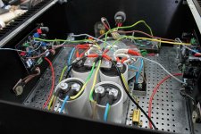
I was just poking around under the hood and found something rather strange. I was measuring voltages at different points in my power supply and found a strange result at the ground terminals.
The power supply is pictured below. The green wire is the ground for the caps and there is an additional wire between the second set of caps (not shown in the picture).
Here is the interesting part: I can measure 7mVDC across the ground terminals on the two caps on the right even though they are directly wired together. In my other two amps, all measurements across the ground terminals show 0mV. I'm thinking it's time to rebuild the power supply in the amp and see how things measure then...
The power supply is pictured below. The green wire is the ground for the caps and there is an additional wire between the second set of caps (not shown in the picture).
An externally hosted image should be here but it was not working when we last tested it.
Here is the interesting part: I can measure 7mVDC across the ground terminals on the two caps on the right even though they are directly wired together. In my other two amps, all measurements across the ground terminals show 0mV. I'm thinking it's time to rebuild the power supply in the amp and see how things measure then...
positive and negative wires can be made in series fashion - from Graetz to cap to cap to resitor to cap
ground wires - bridge between two last caps (pos and neg) , ground wire from CT (or two Graetzs , if you're using that arrangement) to mid point of bridge , and separate ground wires from each cap to mid point of bridge
something like this
then that point - middle of the bridge - is your central ground point
Attachments
Last edited:
Pass DIY Addict
Joined 2000
Paid Member
Choky, do you ever sleep? I thought connecting all of the terminals the way I had would be similar enough to creating a star ground. I suppose this is not the case...
Gotta love the fun of a never ending project 😉
Eric
Gotta love the fun of a never ending project 😉
Eric

Hi Eric,
you could also use a piece aluminium sheet (3mm) to connect all the caps (only the grounds ofcourse).
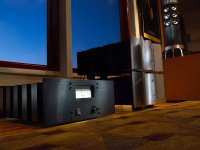
Nice amps on the last pic. Where is it from?
William
you could also use a piece aluminium sheet (3mm) to connect all the caps (only the grounds ofcourse).
Nice amps on the last pic. Where is it from?
William
A big loud speaker.(more articulate than loud)
http://www.6moons.com/audioreviews/firstwatt10/vladimir/credit.jpg
http://www.6moons.com/audioreviews/firstwatt10/vladimir/credit.jpg
- Home
- Amplifiers
- Pass Labs
- Aleph-X builder's thread