Pass DIY Addict
Joined 2000
Paid Member
I substituted two 2SJ74BL parts (2SJ109BL - same specs) for each 9610. So if the 9610 is running 10ma of bias then each JFET will have 5ma of bias. So you need to pick JFET with an Idss higher than that. I'd pick an Idss of 7ma or more. Almost any BL part would work here. The Idss match should be within 10%.
I did what I did to avoid having to change the bias in the diff pair.
Graeme
Hi Graeme,
I just sorted a batch of 2SJ74BL parts (connected for 10s each) and got the following groupings:
1) 8.33mA, 8.32mA, 8.32mA, and 8.31mA - nearly perfect match
2) 9.01mA, 9.00mA, 9.00mA, and 8.81mA - 2.2% match
3) 9.76mA, 9.61mA, 9.46mA, and 9.32mA - 4.5% match
4) 6.98mA, 6.95mA, 6.91mA, and 6.78mA - 2.8% match
Given that I don't want to change the bias of the amp, it looks like any of these groupings will do. Is this correct? I was thinking I would use groups 1, 2, and 4.
Are these matches sufficient for use?
Eric
Pass DIY Addict
Joined 2000
Paid Member
Thanks for the heads up on Borbely's article, William. I found it pretty easily and gave it a read. I think I'll have to go through it a few more times before I really get it all. Not being an EE is a bit of a handicap in this arena...
I was a bit surprised (and pleased) by the groupings that I got from such a small set. Is there any particular way that I should group the FETs in my third set to "even out" the mismatch, or is this unnecessary?
I'm debating picking up a few more devices. This might provide a better match and the left overs might be fun for a rainy day in the future...
Last edited:
Hi Eric,
I remember matching mine (only two per amp) by Idss and Vp and not getting really low offsets. Now I'm using a 10R pot (wiper connected to the current source, the rest to the sources of the fets) to even the imbalance out and set the dc-offset (relative).
If you group them you should try to get even currents on both pairs so maybe the 76 plus 32 and 61 + 46. Then see how the currents are shared.
I would buy a few more. It would be nice to have at least 9mA of Idss when using 5mA bias per fet.
William
Eureka!
Hi,
I´ve observed the amps for a few days now. Sound is very good but the abs. DC offset varies way too much with those McMillans (33k and 39k).
I randomly measured my mains voltage and got results between 226V and 238V resulting in almost 10V of abs. DC offset and some darkened output to ground resistors. (R1,4,44,45).
Not wanting to give up the good sound quality I remembered Patrick suggesting connecting the two Mcmillans to a third resistor which goes to the sources of the input pair and connecting a cap to ground and the point where the 3 resistors meet (See Aleph-J thread) for a sort of DC-Servo.
Unfortunately this gave very interesting signals (a 1.5V triangle at the connection point of the 3 resistors and the cap with a 1V sinus as input) but didn´t work.
Disconnecting the cap made everything work again. Now I measured at the connection of the two McMillans around 0,5% of the output signal (at 2V RMS). This should theoretically be zero. I remember this common mode signal causing the input to shut of when it reached 0,15v (see Aleph-J thread) and cause strange spikes at the output.
So I took them out and measured them. They were 0,43% off which almost fits the common mode "distortion".
Measuring a few 22k resistors I matched a pair to 0,004% (22029R and 22028R). I now this is probably only true for this temp and there are all sorts of other influences but it is much better than just taking two 1% resistors.
Putting them in the amp and measuring again the common mode signal was way lower. Only around 0,15% and never reaching the critical 0,15V (the amp clips before the voltage reaches this value)
To get it even lower I could match better or take a very big pot and put it parallel to one of the McMillans.
For now I will leave it like it is and have a listen. If this common mode is the cause of better sound if you raise the value (the common mode get´s bigger if you lower the value of the McMillans) it should sound better than it did with the unmatched 22k´s. We´ll see.......
And BTW abs. DC offset behaviour is OK now with around 3V for 10V of mains change.
William
Pass DIY Addict
Joined 2000
Paid Member
Wow, after all of that work, it comes down to more careful matching of the McMillan resistors! While my 9610's were very carefully matched when I built my amps (at the 0.1 mV level), I did not match the resistors with the same level of precision. I matched all of my resistors with a 3.5 digit hand held meter. I'll have to visit the EE lab on campus in order to find a 5 digit meter...
Thanks for sharing your results, William!
Thanks for sharing your results, William!
Thanks,
it quite fun at the moment.
I also changed the other channel (with the 33k McMillans) and measured before and after. Before at 2VRMS, 10kHz, in 8R ca. 3.5mV at the diff sources. After around 2.5mV with matched 22k resistors.
Sound is as good as it was before (with the higher McMillans)
abs. DC offset was around -1V at 236V after a few hours, this morning 0V cold @232V
I don´t think I´ve used matched resistors for the input and feedback. Just plain 1% types. Using 0,1% types would probably help too as the left and right half feedback/input probably isn´t exactly equal.
What I will try next is to take a 22k and 24k//2M pot and try to set the common mode to zero at the sources. This would make it possible to use even smaller McMillans. This is probably not neccessary but interesting......
As an alternative I could replace the input and feedback resistors with 0,1% matched ones.
William
Hi,
experimented a little more tonight. Put a 100R pot between the two 22k McMillans and connected the wiper to the JFet sources. This way I wanted to null the resulting signal. (I found out my input/feedback resistors are already 0,1% ones)
Set the amp at 4V rms output, signal at the sources was 4.5mV rms. This signal looks a bit like a sinus with a lot of second harmonic (I´ll post a pic later).
Turning the pot didn´t change anything
After thinking for a little bit longer than it takes to write this down I came to the conclusion that you can only null signals that are 180° out of phase. Signals that are equal on both outputs (real common mode) are not influenced by this. They can only be reduced by raising the value of the McMillan resistors.
So matching the McMillans only reduces the voltage caused by the 180° out of phase output signals not the one caused by real common mode distortion.
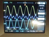
I added both outputs on the scope and got the same signal I see at the JFet sources only 20x bigger. So there seems to be quite a lot of common mode distortion. Not sure where this comes from.......
William
experimented a little more tonight. Put a 100R pot between the two 22k McMillans and connected the wiper to the JFet sources. This way I wanted to null the resulting signal. (I found out my input/feedback resistors are already 0,1% ones)
Set the amp at 4V rms output, signal at the sources was 4.5mV rms. This signal looks a bit like a sinus with a lot of second harmonic (I´ll post a pic later).
Turning the pot didn´t change anything
After thinking for a little bit longer than it takes to write this down I came to the conclusion that you can only null signals that are 180° out of phase. Signals that are equal on both outputs (real common mode) are not influenced by this. They can only be reduced by raising the value of the McMillan resistors.
So matching the McMillans only reduces the voltage caused by the 180° out of phase output signals not the one caused by real common mode distortion.
I added both outputs on the scope and got the same signal I see at the JFet sources only 20x bigger. So there seems to be quite a lot of common mode distortion. Not sure where this comes from.......
William
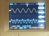
Here are the pics.
The first is 10V rms output
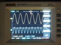
The second around 26V
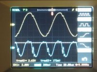
The third almost 30V and clipping
the upper trace is the output (via a voltage divider) and a INA134
the lower trace is where the McMillans meet at the sources
William
The first is 10V rms output
The second around 26V
The third almost 30V and clipping
the upper trace is the output (via a voltage divider) and a INA134
the lower trace is where the McMillans meet at the sources
William
Attachments
Hi,
I added both outputs on the scope and got the same signal I see at the JFet sources only 20x bigger. So there seems to be quite a lot of common mode distortion. Not sure where this comes from.......
William
I've not investigated this in detail but isn't quite a lot of common mode distortion to be expected? The X topology trades lower differential distortion for higher common mode on the grounds that the latter will have no influence on the speaker.
Ian
Pass DIY Addict
Joined 2000
Paid Member
Interesting graphs, William. I am not sure what to make of them..
It is curious, though, every now and then the conversation sends me back to make some more measurements and explore something that I thought I understood some time ago. I was making some minor changes to one of my amps and I decided to go back and study the whole Absolute DC Offset vs. time thing again and this time I also measured temperature. The result was rather interesting:
Time......Offset....Temp
0mins.....14v........13c (ambient)
1min......11.7v......didn't measure
2mins.....10.6v......26c
3mins......9.7v.......30c
4mins......9.0v......didn't measure
5mins......8.3v.......33c
10mins....6.1v.......38c
15mins....5.0v.......45c
30mins....3.7v.......46c
45mins....3.0v.......46c
60mins....2.7v.......46c
90mins....2.5v.......46c
Earlier this summer, I had readjusted my DC offset after 2 hrs to read zero volts (it was off by about 2.5v), but the ambient temp was closer to 19-20c, thus final amp temp was closer to 53-54c. Now that the weather is colder, offset is running about 2.5v higher again.
But the part that stands out to me is the DC offset vs Temp readings in the 15min-90min window. Temp has reached equilibrium, but Absolute DC Offset keeps moving. My current configuration runs 21.5v rails, 8.5A bias, has 10K McMillan resistors, and still uses 9610s as the input differential. House mains voltage seems to move between 122-124vAC depending on the time of day.
Any ideas what is causing offset to move after the amp has reached thermal equilibrium?
Last edited:
Pass DIY Addict
Joined 2000
Paid Member
OK,
Zen is probably right that it is still changing temperatures inside. Mine take a lot longer than an hour.
I´m almost ready with preparations for a dc-servo. I think the amp sounded better with the higher McMillan resistors and I would like to try another solution.
William
Zen is probably right that it is still changing temperatures inside. Mine take a lot longer than an hour.
I´m almost ready with preparations for a dc-servo. I think the amp sounded better with the higher McMillan resistors and I would like to try another solution.
William
- Home
- Amplifiers
- Pass Labs
- Aleph-X builder's thread.