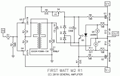
Lm385 is a 3 pin device.
Unless one of the legs is shorted then I'm completely lost. Hahaha
Unless one of the legs is shorted then I'm completely lost. Hahaha
Check the Dumbmeter...
The Dumbmeter you used to assess yourself must be overdue for calibration.
🙂
The Dumbmeter you used to assess yourself must be overdue for calibration.
🙂
Now that I think about it a larger number would make more sense. Less dumb means more smart.
I think I was reading the intelligence meter not the dumb meter. It must be 0.02 PicoSmarts (not very smart).
I'll have a brainwave later and redeem myself for this lack of intelligence.
I think I was reading the intelligence meter not the dumb meter. It must be 0.02 PicoSmarts (not very smart).
I'll have a brainwave later and redeem myself for this lack of intelligence.
Ok. If you short out the adjusting pin thing with the negative thing you get a 1.24V reference.
Need to think about that.
Need to think about that.
Still the same +- 25V.
The M2 is an Amp that runs off 22 to 24V rails
So I got that part right then. Amazing.Q6 and Q7 are LM385-1.2
Hahahaha
I'm thinking it might be beneficial to make R6 45k, assuming P1 sets DC Offset
count on Ugs difference between N and P mosfets , for same current
however , as with all Papa's schematics - count on fact that he's usually taking parts from pre-selected drawers** , so changing any appropriate resistor (say for + or - 10%) if needed on the fly, is trivial thing to him
(one of) purpose(s) of all these schematics thrown on all of us in past few decades is pretty much the same - to same things became trivial to us , too
** he didn't said that , but logic dictates the same, for most cases ;
however , upon completing the amp , if output offset stubbornly stays negative , decrease R6 ; if it stays positive , decrease R7 ; I believe I needed 39K for one , but can't remember which ; even though I used FQP/FQN parts , Geschenk by my älterer Bruder Generg
Last edited:
Q6 and Q7 are LM385-1.2
D1,D2,D3 are 1N4148
Q5 4N35
yeah , stick it to the wall and enjoy sheer beauty
Thanks Zen, I was fixing to ask about the transistors and diodes. What does the red square around Q5 and diode refer to?
Edit, After googling the 4N35 I see it is a 6 pin Optocoupler. Disregard question.
Last edited:
Optocoupler deviceThanks Zen, I was fixing to ask about the transistors and diodes. What does the red square around Q5 and diode refer to?
- Home
- Amplifiers
- Pass Labs
- Official M2 schematic

