
Now that I think about it a larger number would make more sense. Less dumb means more smart.
I think I was reading the intelligence meter not the dumb meter. It must be 0.02 PicoSmarts (not very smart).
I'll have a brainwave later and redeem myself for this lack of intelligence.
I think I was reading the intelligence meter not the dumb meter. It must be 0.02 PicoSmarts (not very smart).
I'll have a brainwave later and redeem myself for this lack of intelligence.
For all the Greedy Boyz,
Voltage PSU?
Still the same +- 25V.
The M2 is an Amp that runs off 22 to 24V rails
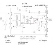
So I got that part right then. Amazing.Q6 and Q7 are LM385-1.2
Hahahaha
I'm thinking it might be beneficial to make R6 45k, assuming P1 sets DC Offset
count on Ugs difference between N and P mosfets , for same current
however , as with all Papa's schematics - count on fact that he's usually taking parts from pre-selected drawers** , so changing any appropriate resistor (say for + or - 10%) if needed on the fly, is trivial thing to him
(one of) purpose(s) of all these schematics thrown on all of us in past few decades is pretty much the same - to same things became trivial to us , too
** he didn't said that , but logic dictates the same, for most cases ;
however , upon completing the amp , if output offset stubbornly stays negative , decrease R6 ; if it stays positive , decrease R7 ; I believe I needed 39K for one , but can't remember which ; even though I used FQP/FQN parts , Geschenk by my älterer Bruder Generg
Last edited:
Q6 and Q7 are LM385-1.2
D1,D2,D3 are 1N4148
Q5 4N35
yeah , stick it to the wall and enjoy sheer beauty
Thanks Zen, I was fixing to ask about the transistors and diodes. What does the red square around Q5 and diode refer to?
Edit, After googling the 4N35 I see it is a 6 pin Optocoupler. Disregard question.
Last edited:
Optocoupler deviceThanks Zen, I was fixing to ask about the transistors and diodes. What does the red square around Q5 and diode refer to?
- Home
- Amplifiers
- Pass Labs
- Official M2 schematic