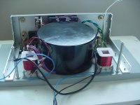
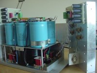
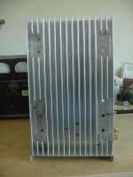
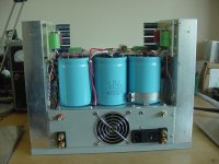
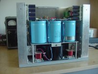
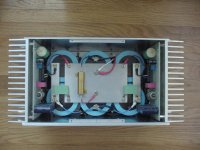
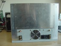
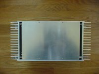
Attached pics. are of the latest incarnation of my 2SK82 power follower design. I have come to the conclusion that the design benefits from a higher B+ and corresponding higher dissipation - approx. 100w per channel. Rather than stick everything in a 5U case I decided to design a more compact fan-cooled chassis. The 12v computer power supply fan is powered from an external wall-wart supply, relay switched from the amp.
Because of my chosen configuration I had to use a cased transformer to direct the airstream to either side where it comes into contact with the SITs. Part of the flow then exits via 'bleed' holes in the heatsink and the rest of the airflow hugs the inside of the heatsink to exit via the slots at the top.
As far as I can measure I have been able to achieve 0.2deg.C/W and the heatsinks are comfortably warm dissipating the combined 200w. The 1/4 inch front and 1/8 inch thick rear faceplates also contribute to the heat dissipation surface area.
I am now a convert to fan-cooling and its benefits in allowing the design of more compact enclosures when there is a need to dissipate serious amounts of class A heat.
Attachments
-
 DSC03334.JPG673.1 KB · Views: 906
 -
 DSC03341.JPG660.7 KB · Views: 393
 -
 DSC03351.JPG679.1 KB · Views: 323
 -
 DSC03349.JPG737.6 KB · Views: 257
 -
 DSC03348.JPG695.8 KB · Views: 301
 -
 DSC03347.JPG713.7 KB · Views: 783
 -
 DSC03346.JPG686.2 KB · Views: 803
 -
 DSC03344.JPG669.2 KB · Views: 829
 -
 DSC03343.JPG672 KB · Views: 860

Interesting 2SK82 amplifier congratulations 
I like a lot big filtering caps , nice build amp !
What is output class A power ?
Schematics be always welcome.
All is perfect is a ready finished version?
What about vfet sound subjective descryption ?
Have a nice day
Best regards
I like a lot big filtering caps , nice build amp !
What is output class A power ?
Schematics be always welcome.
All is perfect is a ready finished version?
What about vfet sound subjective descryption ?
Have a nice day
Best regards

I really hope not, but I strongly suspect that a large part of my motivation in posting is a shameless angling for approbation from the more exalted members of this forum - thank you Zen Mod and Mr. Pass .
Soundhappy - Refer to the thread ' SIT Variations ' for the original schematic. The current design is just a higher voltage version with corresponding higher dissipation. The theoretical output of the design is about 10 watts but realistically, usable output is 5 to 7 watts and that is going downhill with a strong tailwind !
As to sound quality - Few of my DIY attempts make it pass the bread-board stage. Fewer still possess sonic qualities meriting further refinement. That this source follower design is in its 'mark 2' version says something of my regard for its sonic qualities. I am however, not ready to give up on tubes and I am just about to embark on building what I consider to be the ultimate expression of single-ended amplifier design and that is tube based.
Soundhappy - Refer to the thread ' SIT Variations ' for the original schematic. The current design is just a higher voltage version with corresponding higher dissipation. The theoretical output of the design is about 10 watts
Yes i find it !
http://www.diyaudio.com/forums/pass-labs/233057-sit-variations.html
Thanks for your answer
Greetings
n3szd thank you for your kind words. Coming from the opposite end of the amp power spectrum, I have been following your posts with a curiosity bordering on trepidation.
IMO, however outlandish, the DIY community is stimulated and enriched by 'blue sky' musings such as yours - keep it up, let's see where it all leads !
IMO, however outlandish, the DIY community is stimulated and enriched by 'blue sky' musings such as yours - keep it up, let's see where it all leads !
It all leads to Chernobyl 1, a dream of mine for 30 years... Now is the time to make it real. All of our projects are labors of love, even my aleph 3, as a matter of fact my current wife would not marry me if I didn't finish it, and 13 years later it still is awesome!
dare to dream and dream to live,
Rob
dare to dream and dream to live,
Rob
Hi Guys,
I have recently purchased some Yamaha 2sk76 and 2sj26 vfets and am looking to build one of the SIT amp designs.
I read in Nelson's description of the 2sk82, that because it is verticle then the Drain is the case.
Firstly can anyone let me know if the Yamaha's are the same or better still, can you provide the datasheets.
Thanks in advance
Chris
There is not much information on vintage Japanese SITs on the web. The attached is the only info. I have been able to locate.Hi Guys,
I have recently purchased some Yamaha 2sk76 and 2sj26 vfets and am looking to build one of the SIT amp designs.
I read in Nelson's description of the 2sk82, that because it is verticle then the Drain is the case.
Firstly can anyone let me know if the Yamaha's are the same or better still, can you provide the datasheets.
Thanks in advance
Chris
Attachments
Hi Chris, what design are you going to build?Hi Guys,
I have recently purchased some Yamaha 2sk76 and 2sj26 vfets and am looking to build one of the SIT amp designs.
I read in Nelson's description of the 2sk82, that because it is verticle then the Drain is the case.
Firstly can anyone let me know if the Yamaha's are the same or better still, can you provide the datasheets.
Thanks in advance
Chris
Thanks audiong,
That is a help, maybe Hazard can get enough info from that to help with my design.
Now all I need is the pinouts.
Good question Hazard, I was looking at Nelson's push-pull Class A design, I want a bit of power, my speakers are not what you would call efficient.
That is a help, maybe Hazard can get enough info from that to help with my design.
Now all I need is the pinouts.
Good question Hazard, I was looking at Nelson's push-pull Class A design, I want a bit of power, my speakers are not what you would call efficient.
a thing to try is the gate load/bias , with my Sits i have very different sounding results between input caps coupling with bias on the gate with a resistor loading and transformer input coupling with the bias on the secondary. even with 10K input impedance in both case you will have very different beasts .. i can't say wich one is better but it's worth to try
I assume that the cooling for the heat sink is supplied from the chassis below. More efficient cooling could be had by covering up the fins so that the air flow is directed along the entire length of the heat sink before escaping at the top. This way, it may be possible to get by with a lower airflow (read quieter) fan. It's not as pretty/cool looking but thermally efficient. A simple expedient for reducing fan speed would be to feed the fan from the wall wart using an RC filter.
Of course if you're getting sufficient cooling with the present setup, you can ignore this, unless you want to exploit this concept for a smaller heat sink or quieter fan.
Of course if you're getting sufficient cooling with the present setup, you can ignore this, unless you want to exploit this concept for a smaller heat sink or quieter fan.
Excellent suggestions. Early on , I did cover the fins as you suggested (notice the vestigial tapped holes ) but did not notice any significant difference within the limits of my measuring capabilities - I probably needed more bleed air.I assume that the cooling for the heat sink is supplied from the chassis below. More efficient cooling could be had by covering up the fins so that the air flow is directed along the entire length of the heat sink before escaping at the top. This way, it may be possible to get by with a lower airflow (read quieter) fan. It's not as pretty/cool looking but thermally efficient. A simple expedient for reducing fan speed would be to feed the fan from the wall wart using an RC filter.
Of course if you're getting sufficient cooling with the present setup, you can ignore this, unless you want to exploit this concept for a smaller heat sink or quieter fan.
I vary the fan speed using wall warts of differing output voltages and I am currently using 9 volts although I can get by on 6 volts.
An unanticipated benefit of the current design ( as opposed to the traditional forced-air tunnel heatsink) is that in the event of fan failure, the side-moumted heatsinks retain their function as passive units and although they do get very hot I guesstimate that the devices should be able to survive a listening session or at least until such time as the fan failure is noticed.
Anyway thanks for your input.
It might be interesting to try using a centrifugal blower to pressurize the case rather than the usual axial blower. They can move air against higher back pressure better than an axial blower. I have a few DC centrifugal blowers from various surplus sources that I intend to try on an appropriate project.
- Status
- This old topic is closed. If you want to reopen this topic, contact a moderator using the "Report Post" button.
- Home
- Amplifiers
- Pass Labs
- SIT Power Follower revisited