Correct SilasmellorOnly to occupy your handsall the more reason to keep building things...
Im currently thinking of a chassis for M2 monoblocks and really like how the Hiraga Monsters and for example the Pioneer M22 class A from the eighties where built. More in the tube style with exposed caps and trafoboxes. I really lusted for the Hiraga amps when I was studying in Dk in the eighties. Couldnt afford the amps or the right speakers at the time and eg the Acoustas with the 8 inch Corals, which I could have built, where to thin sounding for my taste. I did assemble the Klifoth Onkens ( with the plaster egg) for a friend, they would have been great partners for the Monsters.... I tried yesterday to exchange my Aikido linestage ( ca 10-15 db gain, using 4x 6cg7 tubes) with a Slagle autoformer box ( used as my pre for many years in front of SE 300B amps). ...
You could try re-configuring your Aikido as an Aikido Cathode Follower (ACF), which mainly acts as a buffer.
I did that by pulling out the first tube, the one that provides all the gain. The only thing that I then needed to do then was connecting the two connections in the empty socket where grid and plate of the lower half of the tube would have been going with a capacitor. 220 nF to 1 µF is fine, and voltage rating must be sufficient for the full B+.
in the attached schematic, the left socket would be empty, and the capacitor would go between pins 1 and 2.
Just try it ... it's an interesting alternative. It gives me enough gain in most situations (M2 into 100dB/W efficient Jericho Horns), and has about half the distortion of a regular Aikido.
Just remember that the regular Aikido is inverting, but the ACF is not ...
Best regards,
Claas
Attachments
Lower voltage rail, higher bias
Friends,
Anyone tried with lower voltage rails, like around +/- 19-20V, and higher bias point of 1.5 amps or slightly more? I am guessing the THD profile would change a slightly, maybe also the DF, and the amplifier would sound a bit different?
Friends,
Anyone tried with lower voltage rails, like around +/- 19-20V, and higher bias point of 1.5 amps or slightly more? I am guessing the THD profile would change a slightly, maybe also the DF, and the amplifier would sound a bit different?
I finally got around to making the modifications to my F6 as suggested by 2 picoDumbs before the Xmas holiday. This involved adding a 0.1 Ohm resistor between the source of Q1 and the lower leg of C1. Now the R1 position totals 0.5 Ohms, and the R2 position is 0.4 Ohms, as before. The difference is the connection of C1. I used a basic metal oxide 5%, 1W resistor that I already had available for the 0.1 Ω value. This is all as recommended in F6 Amplifier
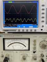
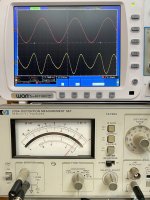
As usual, the amp needed an overnight burn-in to settle into the new configuration. To my ears, the difference was somewhat subtle in this morning's listening session. Yesterday afternoon, it was less subtle. Next I needed to hook the amp up to my distortion analyzer to see how it measures. The pictures below show distortion measurements at 5 Watts output power. The first picture was the original amp, and the second picture is the most recent mod.
At 5 Watts, the THD has increased from 0.07% to 0.28%. The distortion is now predominately H2, which is to be expected with this modification. At 1 Watt output power, the distortion is also predominately H2, but 0.12% instead of 0.022% from the previous configuration.
I probably need to spend more time listening to the amp before deciding whether or not to keep the modification. I am also still working through some tweaks to the bias current, so it might be interesting to see how that folds into the mixture.
Attachments
There is no right or wrong just tweaking to your own personal.preference.
+1
I finally got around to making the modifications to my F6 as suggested by 2 picoDumbs before the Xmas holiday.
I probably need to spend more time listening to the amp before deciding whether or not to keep the modification. I am also still working through some tweaks to the bias current, so it might be interesting to see how that folds into the mixture.
Yeah live with it for a few days.
What bias are you at now?
Bumping it up to 1.8A should be straight forward.
Whatever happened to the idea of added positive feedback, like the F7?
It’s not the best example to use positive feedback because of the low bandwidth. PCF will reduce it further.
Better off going with more negative feedback (higher, bias, higher transconductance parts etc) as it improves everything.
The amp has lower feedback than F5 or J2 so adding a bit more is not such a bad thing.
I'm now listening to the new configuration. I had a couple 0.22Ω, 1W resistors available, so I soldered those in parallel with the 0.1Ω resistors added earlier. That makes 68 mOhms in this location. I also changed the gate stoppers for Q1 and Q2 to 120 Ohms instead of 220.Maybe try dropping from 100mOhms to 50mOhms.
I have one more idea after that.
There is no right or wrong just tweaking to your own personal.preference.
After some adjustment and bench top burn in, the amp has settled in to 1.75 A quiescent current and < 10 mV offset. The higher bias definitely needs a longer warm up period before the amp reaches thermal equilibrium, but it's worth the wait. We seem to have arrived at a happy medium between being a little 'dry' and having too much H2. I haven't measured the THD, but may postpone that indefinitely, or until my curiosity gets the better of me..
There seems to be some "conventional wisdom" that the gate stoppers don't make a difference in how an amp sounds, as long as they are within a certain range. I would amend that to say the difference is subtle, but worth trying. In this case, with the last couple circuit parameters being dialed in through small adjustments, I'm glad I made the change. The enhanced bass response has tended to make my hotrod F6 sound a little dark. Reducing the gate stoppers has opened up the top end just slightly. I will of course continue to listen as the amp gets more play time, but the balance seems to be just right now.
One of the defining characteristic of this amp that has remained present through its evolution is its extended and well controlled bass. With the current tonal balance, this works well with a variety of styles of music, and makes me appreciate have a set of large, full-range speakers. I have a large living room, so filling it with music this way is a whole lot of fun.
Nice work.I'm now listening to the new configuration. I had a couple 0.22Ω, 1W resistors available, so I soldered those in parallel with the 0.1Ω resistors added earlier. That makes 68 mOhms in this location. I also changed the gate stoppers for Q1 and Q2 to 120 Ohms instead of 220.
After some adjustment and bench top burn in, the amp has settled in to 1.75 A quiescent current and < 10 mV offset. The higher bias definitely needs a longer warm up period before the amp reaches thermal equilibrium, but it's worth the wait. We seem to have arrived at a happy medium between being a little 'dry' and having too much H2.
There seems to be some "conventional wisdom" that the gate stoppers don't make a difference in how an amp sounds, as long as they are within a certain range. I would amend that to say the difference is subtle, but worth trying.
One of the defining characteristic of this amp that has remained present through its evolution is its extended and well controlled bass. With the current tonal balance
I would even go lower with the gate stoppers to 47 Ohms or 22 Ohms.
What zener references are you using for biasing?
When you say thermal equilibrium are you referring to bias drift as the amp heats up or just literally for the heat sinks to reach thermal equilibrium?
Last edited:
I am using LM329 voltage references. I wanted to make sure I could turn on the FQH44N10 devices hard enough.
As I recall, the lower gate stopper values were used for the original power JFets in Nelson's prototype F6. I normally use between 120 and 220 Ohms for power Mosefets. We'll see how things sound after the amp has had more time to settle in. My power supplies have settled down to +/– 26.2 Volts with the increased quiescent current.
My speakers are the old Vandersteen 2C. Every time I think about replacing these, I get sticker shock over a suitable replacement. (The ATC SCM40 has come to mind.) Then I make a change to one of my amps, and it's like I have new speakers again. I'm probably more inclined to just get the latest version of the Vandersteens, which would be the 2ce Signature II.
I wouldn't say that thermal drift is a problem, just that the whole amp takes a long time to thermally stabilize. In addition to the output devices dumping a little over 45 W each onto the main heatsinks, the CapMx devices are also dissipating about 3.6 W for each rail (four of them for dual-mono), plus the power transformers eventually get warm as well. I guess it's a matter of perspective. I did drill a few more holes in the base plate before the most recent assembly.
I'm used to leaving my amps on all the time, though the F6 is now running a little hotter than my Aleph J. The LVB2650 rectifiers inside the J are too hot to touch for more than 1 second, but that's how they sound best. Living in the Seattle area, having a nice little 200W space heater in the corner of my living room is no big deal.
I'm used to leaving my amps on all the time, though the F6 is now running a little hotter than my Aleph J. The LVB2650 rectifiers inside the J are too hot to touch for more than 1 second, but that's how they sound best. Living in the Seattle area, having a nice little 200W space heater in the corner of my living room is no big deal.
- Home
- Amplifiers
- Pass Labs
- The diyAudio Firstwatt F6