it's already made by Pa ( and numerous times before) , sans output xformer
Pa's is called F6
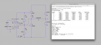
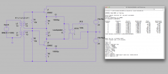
I tried F6 type connection (transformer polarity reversed) without the Parafeed Choke, but the THD figure was mostly 3rd harmonics (PP) on LT Spice. Is it possible doing SE connection without the choke?
Well, I had thought it would be nice because I don't have to buy another Choke and can re-use FirstWatt PSU , but after thinking again, parallel SE would be simpler and less costly at the end. 
EDIT, One good thing about this is probably it has 2x mu and headroom, since 2SK82 has very low mu and low headroom.... I will compare parallel and this on LTSpice.
EDIT, One good thing about this is probably it has 2x mu and headroom, since 2SK82 has very low mu and low headroom.... I will compare parallel and this on LTSpice.
Last edited:
que ?
I'm not following you with "SE connection" ...
The output of J1 and J2 is opposite phase. Tube Cad calls this circuit single ended, so I just followed their definition... Sorry for the confusion!
Last edited:
The output of J1 and J2 is opposite phase. Tube Cad calls this circuit single ended, so I just followed their definition... Sorry for the confusion!
he needs choke/xformer for transforming impedance ; what is drawn , when transfered in sand realm , is nothing else than F6 ; character of amp ( 2nd dominant , 3rd dominant) is easy to set with different values for source resistors or even with Zen Amount Pot ; search in F6 thread
Jack is still in charge.
didn't expected anything else
Last edited:
Thank you, ZM (as always!).character of amp ( 2nd dominant , 3rd dominant) is easy to set with different values for source resistors
Now I tried that on LTSpice (If I understand your words correctly...) , but it seems like the virtual sands are way too accurate to replicate the real thing even with the 2SK82s with intentionally different curves.
Looks like I should prototype the real thing.
Attachments
stay with gate biasing , and keep source resistors at minimum , increasing only what you need to get preferred THD spectra
if you bias them with source resistors you're wasting gain and getting awful DC offset at output ........ meaning - it's not practical chasing both THD spectra and 0 offset in same time with same parts
if you bias them with source resistors you're wasting gain and getting awful DC offset at output ........ meaning - it's not practical chasing both THD spectra and 0 offset in same time with same parts
stay with gate biasing , and keep source resistors at minimum , increasing only what you need to get preferred THD spectra
if you bias them with source resistors you're wasting gain and getting awful DC offset at output ........ meaning - it's not practical chasing both THD spectra and 0 offset in same time with same parts
Thank you for your advice again.
Sure, I understand the offset part.
1 or 2 ohm would be a reasonable value to start experiments?
it's cheap in LTSpice to change them
Yep, but don't worry, I love resistors.
Attachments
hmm, I'm going back and forth. After seeing the ultra simple self biased version, it's hard to go back to the fixed bias one!
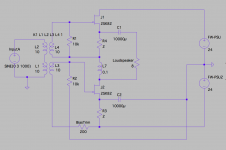
The problem is the gain loss that ZM pointed out, so I brought back the choke again. My novice brain could not find any other way to realize a self biased version with high gain...
I can do this now with my parts in my drawer, so I probably should try this first. If you guys find any issue, or have better idea, please let me know.
(VCVS and R10 is to measure THD)
Attachments
Last edited:
Yep, but don't worry, I love resistors.
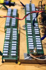
Beast of a thousand resistors.
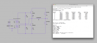
After a bit more careful examination, I concluded that this accordion topology would not a good idea for 2SK82, because the output impedance is too high (15 ohm-isn). It would be OK for 16 ohm speakers, but those speakers would not need high power anyway. The best results on simulations were CSX and ZM suggested F6 kind with 0.1 -0.2 ohm source resistors.
For those adding a buffer before the transformer, what load is reasonable to test the buffer distortion with? I have tested 1000 and 500 load and I am happy with how the buffer is performing. I could connect it to my transformer to further test and terminate the transformer with two resistors (what value?) to provide an even more realistic test scenario?
There is a nominal impedance for the transformer primaries, but that's for when
the secondaries are driving their rated impedance, which in these instances
they usually aren't.
With the 150:150:150:150 ohm line transformers we've been using as
autoformers, I have measured mid-band impedances of 5K or so. If you
can drive 500 ohms without significant distortion, you are doing fine.
For maximum bandwidth you want buffers that have output impedances
lower than the DC values of the primaries. For the Jensen and Cinemag
examples, 25 ohm is desirable, although things don't fall apart until quite
a bit higher.
- Status
- This old topic is closed. If you want to reopen this topic, contact a moderator using the "Report Post" button.
- Home
- Amplifiers
- Pass Labs
- Article - Sony VFETs part 1