why not checking in TL431 datasheet , and having some faith in own conclusions .......

Hahaha, well yes that is exactly what I should do I suppose. Us greedy boyz can get just a bit lazy sometimes and ask questions here to shortcut having to do our own thinking
")
I will pull up the datasheet and do the calculations. Likely it will take less than 5 minutes to do...
you always have 2.5V between adj and lower terminal
resistor in between is setting current through "adj. rail"
so , you put upper resistor , current is set by lower one , then voltages across resistors is matter of proportion
sum voltage is ...... just sum
series resistor for entire combo is allowing/setting overal current for TL431 itself , resistor divider , and loading stage/consumer
simple , isn't it
edit : just do not overcook voltage A-K , not overcook max current , not overcook resistors , and you're good
Last edited:
OK, so I did what I should in the first instance and did the calculations. I plugged it into Excel so that I could see what happens if I change R5 (3K3) and R7 (7K5) for different values of the potentiometer P1.
I can get a couple of extra volts bias and stay within the Imin for the TL431 if I drop the supply resistor (R5) and increase R7. 2K and 10K respectively look like it will work.
I will make the changes tonight and check the results.
Thanks Zen Mod!
I can get a couple of extra volts bias and stay within the Imin for the TL431 if I drop the supply resistor (R5) and increase R7. 2K and 10K respectively look like it will work.
I will make the changes tonight and check the results.
Thanks Zen Mod!
I am hoping to bias it at ~0.8A, so pretty low. This amp will just feed a tweeter in a 3-way setup so it doesn't need much grunt and I'd rather run it at a lower bias for longevity.
What are the values of your supply rails?
What are the values of your supply rails?
The main PSU is +/-24V or thereabouts (maybe +/-23.5V).
For the bias I am using 12V secondaries which give around 18V rectified DC so the TL431 needs to work with that to develop the bias.
Maybe I should just bias the amp a little higher, it is in a 4U 400mm deep chassis (from Modushop/HiFi-2000) so should easily cope with 1.2A or higher.
As said though, I don't need a lot of power from this amp at all. This will be feeding a 4 ohm planar tweeter crossed at 3100Hz (LR4 crossover). After a bit of reading a highpass driver over ~3000Hz only requires ~15% of total power for white noise - hence why I don't think I'll need a lot of grunt.
Are there other reasons to bias higher, nearer the specified 1.5A?
practically 500mV as transitional , and up to 100mV in temp. equilibrium
at least values acceptable for me
(remember that Papa is FAB (Numero Uno) , don't be surprised if he just erase m from my figures )
)
edit - for transitional value , it can go even higher , what's important is steepness of it - if DC arrives gentle , it's less critical
at least values acceptable for me
(remember that Papa is FAB (Numero Uno) , don't be surprised if he just erase m from my figures
)edit - for transitional value , it can go even higher , what's important is steepness of it - if DC arrives gentle , it's less critical
Last edited:
Adoption
ZM, Your chances for adoption were never in doubt. Now proof! H.
ya bet .........
it's stressful ...... every time I answer on something directed to Pa , I'm expecting a slap in next 3 hours (each time further diminishing my chances for adoption)
ZM, Your chances for adoption were never in doubt. Now proof! H.

VFET Accordion Amp
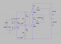
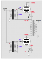
I was reading TubeCad last night, and I thought Accordion Amp topology would be suitable for VFET single ended amp. LTSpice simulation suggests 2x Mu, 2X wattage than regular Sony 2SK82 SE amp, and typical SE THD figure.
I don't know if this amp works good in real world, so I ll appreciate it if someone would give me an advice. The Choke in the schematics is 0.15H 1 ohm, and R3 is for voltage compensation. Maybe a bad idea...
The Tube CAD Journal: The Accordion Amplifier: A new single-ended topology
Attachments
Last edited:
- Status
- This old topic is closed. If you want to reopen this topic, contact a moderator using the "Report Post" button.
- Home
- Amplifiers
- Pass Labs
- Article - Sony VFETs part 1