I have a question about powersupply to Aleph 1.7 pre
my trafo gives about 66vac out,,,it gives messured close to 98 vdc out of diode and cap-
it is close to the 100v value off the panasonic fc caps
to give a bit lower volt i have placed 2 resistor in the ac line after the trafo (4.7ohm)
this give about 94vdc
Is it ok to use resistor in the ac line after the trafo ??? sound wise..data wise
Trafo is 240va
Bjarne
Yes, you can use a resistor in the AC or after rectification. Papa himself did that with the A75 supply with resistors feeding the voltage doubler for the front end power supply. Just leave enough room between resistor and board for air to circulate and not burn your boards.
Some will say you are pushing a bit close to the capacitors' rating even dropping to 94V. You may find that you need to replace them sooner than you would with higher rated capacitors, say 20%+ over operating voltage. In home use this could translate into 10-15 years instead of 20+. I don't know for sure but I think we tend to go a bit overboard derating sometimes. Take a look at the datasheets to get a clue how the life might be affected.
Some will say you are pushing a bit close to the capacitors' rating even dropping to 94V. You may find that you need to replace them sooner than you would with higher rated capacitors, say 20%+ over operating voltage. In home use this could translate into 10-15 years instead of 20+. I don't know for sure but I think we tend to go a bit overboard derating sometimes. Take a look at the datasheets to get a clue how the life might be affected.
I think i must drop to use this trafo--the serie resistor have to be to big..some time in the night time i messure about 99v....this is not so good for the caps
instead i will use 2 trafo with a lower volt ..dual mono
i am building a Veteran Aleph ..so i can compare to KK board..just need some parts to finish it
on the Veteran board i use other resistor type...Vishay Ero caps (15uf 100v)
be fun to hear it
instead i will use 2 trafo with a lower volt ..dual mono
i am building a Veteran Aleph ..so i can compare to KK board..just need some parts to finish it
on the Veteran board i use other resistor type...Vishay Ero caps (15uf 100v)
be fun to hear it
Hi Folks,
can anyone help me figure out how to wire this :http://www.mouser.com/ds/2/128/c4-8997.pdf to a balanced ALPS pot please ?
Thanks ,Rich
can anyone help me figure out how to wire this :http://www.mouser.com/ds/2/128/c4-8997.pdf to a balanced ALPS pot please ?
Thanks ,Rich
balanced route is having two poles phases : one + , one -
just imagine it as plain stereo , with + as R and - as L channel
so , wire it as plain stereo pot
for stereo balanced , that's as two stereo pots on one shaft
all that , speaking of common (meaning - usual ) L (shaped) attenuator
there are other types , but that one is good enough for starters
just imagine it as plain stereo , with + as R and - as L channel
so , wire it as plain stereo pot
for stereo balanced , that's as two stereo pots on one shaft
all that , speaking of common (meaning - usual ) L (shaped) attenuator
there are other types , but that one is good enough for starters
I have 3 rows of 4 pins and 3 rows of 8 pins … The row of 4 i'm understanding to be 1 input +/- , +/- …. The rows of 8 … are my common ground ? and ? …. thats not it ") I have 12 positions ??? The above is only 9 .
I have 12 positions ??? The above is only 9 .
I'm lost now ……
BTW, I'm using 3 inputs balanced .
Sorry to make a mess of this thread …. !
Rich
I have 12 positions ??? The above is only 9 .I'm lost now ……
BTW, I'm using 3 inputs balanced .
Sorry to make a mess of this thread …. !
Rich
Attachments
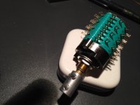
12 position , 4 decks
use datasheet ,ohmmeter , paper and pen - to determine pinout
I'm not capable to think without all that

Hi all, I have gotten a set of boards for this preamp, made by "Veteran", and am looking forward to hearing it. I hope this is a good spot to post a couple questions about it. If not, sorry for this.
The the input impedance of this unit is R3, R4 and R5 in parallel, right? ignoring the little switchy input pad. I have a complicated reason for wanting to make R4 an R5 much larger, (so that the value of input impedance is dominated by R3). R4 and R5 form a voltage divider which provides bias to the gate of the MOSFET. Perhaps, there is also a little signal feedback too? I'm not too sure about that though.
I see a couple options - one is to simply make R4 and R5 very large, like an order of magnitude larger. 2Meg. Another is to keep them as is, fly the node of R4 and R5 off the board, and feed that bias voltage to the gate through a single 1M resistor. I hope I've explained this clearly. I understand there will probably be some noise penalty. I'm wondering, how bad? and, is there some other reason I'm not seeing, why this is an unworkable idea?
Also, I was thinking about having a couple relays that operate in concert with the source selector relays, to automatically switch in different values for the gain setting resistance (a 2Kohm pot in the schematic) for different audio sources. Is that a bad idea?
Thank you Thank you Thank you! for any insights.
- Status
- This old topic is closed. If you want to reopen this topic, contact a moderator using the "Report Post" button.
- Home
- Amplifiers
- Pass Labs
- Aleph P 1.7 stereo preamplifier.....