To dampen or not the motion of the woofer
The principal variable in both images was the setup of the left image used a diminished woofer damping [R=12 Ohms], versus the setup of the right image where the damping of the amplifier was not perturbed or was maxed. The performance of the setup of the right image is inferior to that of the left image The sum of the reduction in SPL of the right image = 29 dB. A 20 dB difference in performance between the two setups is outside the bounds of experimental error.
A diminished damping of the woofer appeared to be the better approach than higher option to maximize the reduction is SPL of standing waves in corners.
Attachments
Here are additional details for the DIYer who wishes to assemble this DIY:
1. The stereo receiver need not be high power like the Kenwood KR-6050. My feel is that a 5-10 W/Ch Class AB system will be fully adequate. The scope signals I watched during these studies were in the range of 40 -80 mV peak to peak across the loudspeaker.
2. The relevant subsystems in a receiver are: [Aux, Tone amp/Bass and Volume controls]. These functions are readily available in non-receiver systems. For example, like a Pyramid PB 440X automotive stereo amp I have. The Bass boost [on Kenwood] gave me performance between 40 and 30 Hz. Treble control was left in the neutral position as its didn't have any actual impact.
3. The woofer requires a low pass x-over filter as Pass talked about earlier. It need not be a DVC either like I've used.
4. The power resistor [e.g. 12 Ohms] in series with the woofer protects it from the wrath of an inadvertent oscillating amp.
5. May have to tweak the power resistor in series with the woofer so as to maximize SPL reduction of standing waves.
Reviving an old experiment
The following is the start of a comprehensive performance characterization of the Acoustic Absorber [AcAb] which uses a DVC subwoofer in which one voice coil acts as a moving coil microphone, and its twin as a loudspeaker.
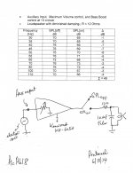
In this study, performance will be established in the frequency range of 35-100 Hz instead of the single frequency approach [deficient] done in previous experiments. The following image shows the diagram/schematic of the test equipment. It does not look as simple as that of the system I described earlier using an electret microphone. But, the difference between an electret and a voice coil as microphones is more like the difference between an apple and beef! This current system must perform to warrant its added complexity.
The top part of the image has been assembled an is stable as shown. The volume control and the step-down iron core power transformer were a must to achieve stability and control over an expected oscillation.
1. The DVC subwoofer sat in the left corner of the room. A sound pressure meter faced the driver, and was set on the 70 dB scale.
2. As the volume control [25 Ohm] was increased at the input of Threshold S/150, a point is reached whereby the onset of oscillation [shriek] is readily seen on the scope. Simply back off the volume a smidgen.
3. The switch at the power output of S/150 was to simply pull the banana plug of the cord going to the step-down transformer. In this OFF position, the room was stimulated with standing waves [SW] at a set frequency, and sound pressure was adjusted to 70 dB [mid scale of meter] so as to establish a start point. The banana plug was inserted next in the amp's port [Pass patent] and the change in sound pressure recorded.
4. Another important value of the step-down transformer is isolation and providing a line-level signal [Vs] which fed a second assistant amplifier and loudspeaker which sat next to the DVC subwoofer.
5. This line-level signal [Vs] describes or exactly mirrors what's happening in the corner vis a vis disrupting or attenuating SWs. This assistant system amplifies this faithful signal so as to further boost the disruption of SWs.
So, in the next post, we will see the performance the system pertaining to the upper diagram only, and make sense out of it.
Best regards.
The following is the start of a comprehensive performance characterization of the Acoustic Absorber [AcAb] which uses a DVC subwoofer in which one voice coil acts as a moving coil microphone, and its twin as a loudspeaker.
In this study, performance will be established in the frequency range of 35-100 Hz instead of the single frequency approach [deficient] done in previous experiments. The following image shows the diagram/schematic of the test equipment. It does not look as simple as that of the system I described earlier using an electret microphone. But, the difference between an electret and a voice coil as microphones is more like the difference between an apple and beef! This current system must perform to warrant its added complexity.
The top part of the image has been assembled an is stable as shown. The volume control and the step-down iron core power transformer were a must to achieve stability and control over an expected oscillation.
1. The DVC subwoofer sat in the left corner of the room. A sound pressure meter faced the driver, and was set on the 70 dB scale.
2. As the volume control [25 Ohm] was increased at the input of Threshold S/150, a point is reached whereby the onset of oscillation [shriek] is readily seen on the scope. Simply back off the volume a smidgen.
3. The switch at the power output of S/150 was to simply pull the banana plug of the cord going to the step-down transformer. In this OFF position, the room was stimulated with standing waves [SW] at a set frequency, and sound pressure was adjusted to 70 dB [mid scale of meter] so as to establish a start point. The banana plug was inserted next in the amp's port [Pass patent] and the change in sound pressure recorded.
4. Another important value of the step-down transformer is isolation and providing a line-level signal [Vs] which fed a second assistant amplifier and loudspeaker which sat next to the DVC subwoofer.
5. This line-level signal [Vs] describes or exactly mirrors what's happening in the corner vis a vis disrupting or attenuating SWs. This assistant system amplifies this faithful signal so as to further boost the disruption of SWs.
So, in the next post, we will see the performance the system pertaining to the upper diagram only, and make sense out of it.
Best regards.
Attachments
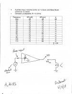
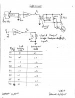
The top part of attached image shows the diagram of the Acoustic Absorber [AcAb] which utilizes a DVC subwoofer. Voice coil 1 [VC1] is the moving coil microphone, and VC2 is the loudspeaker. Note the following:
1. The room was stimulated with sound, and the sound pressure meter was set to the 70 dB scale with the switch OFF at the output of the amp.
2. Sound pressure was recorded with the switch in the ON position, and from it was subtracted sound pressure in the OFF position to give Delta dB.
3. Delta dB was plot versus the stimulation frequency in the range of 35-60 Hz. This is shown at the bottom of the image.
4. A Bass Boost was observed in the frequency range of 35 - 40 Hz. This unexpected outcome was not the Pass invention.
5. A Bass Cut or the disruption of corner standing waves [Pass patent] was observed in the range of 45 - 60 Hz. The transition between Boost to Cut was sharp as shown in the graph.
Consequently, AcAb22 showed a dual function. The Bass Boost property may be useful to loudspeakers which have an intrinsic weak output in this range.
The voltage measurements above the schematic were collected using the scope at 45 Hz where a maximum disruption of standing waves occured. Note the ratio of V3/V1 = 20 which was ~ the voltage gain of S/150. Most important was the ratio of V4/V1 = 2.5. This was the maximum and stable [against oscillation] stepdown ratio of the internal transformer [VC2 to VC1]. This ratio of of V4/V1 = 2.5 was constant in the range of 35-60 Hz.
The above performance was readily amplified. Results are forthcoming.
Attachments
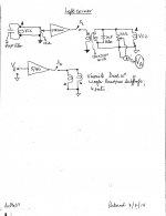
A Stereo Acoustic Absorber
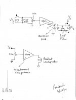
The diagrams [2 images] of this stereo Acoustic Absorber [AcAb of standing waves in corners] appear complicated. Fortunately this DIY is not, and is actually a beginner's project; as one will be assembling wires, volume controls, transformers etc. However, it has several bulky components [sub woofers], and over rated amplifiers; which I had idle for sometime, and now I put to good use. This system is simple, versatile to integrate and tweak [optimize performance], and further gave me objective data and subjective impressions. The system worked as shown and was stable against oscillations. Please look at the top diagram of AcAb used for the Left corner. I showed an equivalent of it in Post#63.
1. A DVC subwoofer sits smack in the left corner. Voice coil 1 [VC1] drives a utility voltage source amp [75 W/Ch..overkill] which is the power amp of the receiver STA 2000 from Radio Shack. The signal from VC1 did not pass through a tone amp; but fed directly the input of the PA.
2. Switch 1 [S1] at the amp's power output is STA's on/off speaker switch which is convenient.
3. The amp's power is stepped down [~5:1] via the 50 VA iron core AC power transformer. The power signal from the trans's secondary was fed to VC2 so as to be in phase with that on VC1 [positive feedback per the Pass patent].
4. A line level signal [Va] was derived at this secondary winding via the volume control [25 Ohm] which is a must for tweaking. This signal energized the power amp [Threshold S/150] which drove the Visonik bandpass subwoofer so as to assist [aka amplify] the performance of the Primary AcAb [points 1-3]. Visonik sits next to DVC subswoofer.
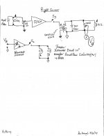
The Right corner AcAb [Right image] is like that of the left corner. But, its Primary AcAb used S/150 amp, and Kenwood KR6050 was the Assist Amp. Note this versatility of swapping the role of S/150 from Primary AcAb to Assit system. The Left and Right corner channels need not be identical vis a vis their components; as long as their resultant performance are similar and/or tweaked via the volume controls to be similar. Note that the Assist line level signal passed through the Tone amp of Kenwood; broadening the scope of use without detriment.
I'll show the objective performance of the Left corner AcAb in the upcoming post. I'll also talk more about my subjective impressions due to this stereo AcAb. This stereo system removed Bass energy from the room, which was readily perceptible when I listened to music.
Best regards.
The diagrams [2 images] of this stereo Acoustic Absorber [AcAb of standing waves in corners] appear complicated. Fortunately this DIY is not, and is actually a beginner's project; as one will be assembling wires, volume controls, transformers etc. However, it has several bulky components [sub woofers], and over rated amplifiers; which I had idle for sometime, and now I put to good use. This system is simple, versatile to integrate and tweak [optimize performance], and further gave me objective data and subjective impressions. The system worked as shown and was stable against oscillations. Please look at the top diagram of AcAb used for the Left corner. I showed an equivalent of it in Post#63.
1. A DVC subwoofer sits smack in the left corner. Voice coil 1 [VC1] drives a utility voltage source amp [75 W/Ch..overkill] which is the power amp of the receiver STA 2000 from Radio Shack. The signal from VC1 did not pass through a tone amp; but fed directly the input of the PA.
2. Switch 1 [S1] at the amp's power output is STA's on/off speaker switch which is convenient.
3. The amp's power is stepped down [~5:1] via the 50 VA iron core AC power transformer. The power signal from the trans's secondary was fed to VC2 so as to be in phase with that on VC1 [positive feedback per the Pass patent].
4. A line level signal [Va] was derived at this secondary winding via the volume control [25 Ohm] which is a must for tweaking. This signal energized the power amp [Threshold S/150] which drove the Visonik bandpass subwoofer so as to assist [aka amplify] the performance of the Primary AcAb [points 1-3]. Visonik sits next to DVC subswoofer.
The Right corner AcAb [Right image] is like that of the left corner. But, its Primary AcAb used S/150 amp, and Kenwood KR6050 was the Assist Amp. Note this versatility of swapping the role of S/150 from Primary AcAb to Assit system. The Left and Right corner channels need not be identical vis a vis their components; as long as their resultant performance are similar and/or tweaked via the volume controls to be similar. Note that the Assist line level signal passed through the Tone amp of Kenwood; broadening the scope of use without detriment.
I'll show the objective performance of the Left corner AcAb in the upcoming post. I'll also talk more about my subjective impressions due to this stereo AcAb. This stereo system removed Bass energy from the room, which was readily perceptible when I listened to music.
Best regards.
Attachments
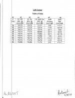
Data for Left Corner Acoustic Absorber
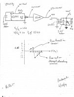
The attached two images show the performance of the Left Corner Acoustic Absorber [AcAb]. The Left image is a Table of the collected data; meaning sound pressure versus frequency in the 35-80 Hz range. The top part of the right image is the diagram of the assembled components making up the Net AcAb. Please note the following:
1. The Right Corner AcAb was offline during the data collection.
2. The DVC sub woofer, STA2000, and the step down transformer make up the Primary AcAb.
3. The bandpass subwoofer [BP] and its S/150 amp are called the Assist system
4. The Primay AcAb and the Assist system are referred as the Net AcAb.
5. The 25 Ohm pot at the input of STA2000 has this unique role. It was advanced from ground upward so as to reach a point very close to where this Primary AcAb oscillated. Must meet this condition before one gets the performance for the Primary AcAb.
6. The room is next bathed with a low frequency [e.g. 45 Hz]. The switches S1 [on STA2000] and S2 on S/150 were both in the OFF position.
7. Sound pressure was measured at the DVC and BP sub woofers to give the result [e.g. 45 Hz.] in column #2 of the Table in left image.
8. S1 was closed next , and the new sound pressure at DVC and BP subs was recorded.
9. The algebraic difference between the sound pressure with S1 Off and On at DVC and BP gave the result in column #5.
10. The 25 Ohm pot across the secondary of the power transformer generated the line level signal Va which fed S/150 Assist system. It has a role unrelated to that at the input of STA2000.
11. S1 and now S2 are closed. the Assist pot started at ground level and then advanced [no fear of oscillation] so as to enable or force the DVC and BP subs to work together rather than oppose each other.
12. Work together means that after the results in column #4 were collected and the delta dB output calculated in column #6, the algebraic sign attendant to each number was the same at all frequencies tested. Intuitively, if DVC had a plus delta dB and BP had a simultaneous minus delta dB at a certain frequency, the subs opposed each other's effort to disrupt standing waves.
13. At 45 Hz, the delta dB of -4 and +/-zero were OK.
14. I did steps 11-13 three times [tweaking the pot at input of S/150] in order to get the best results in column #6.
15. The delta dB result [column #6] at each frequency for DVC and BP were added together and then divided by two to generate a new column of numbers called the Average Net delta dB. This is the far right column in the table underneath the diagram /schematic of Net AcAb.
16. A comparison of the delta dB numbers of Average Net with the corresponding Primary results [just DVC in column #5 in Table of raw data] showed augmentation in performance which was the objective I needed to demonstrate, and use practically.
17. The Net AcAb was stable, and trustworthy because it operated for long periods of time without oscillation.
More to post.. Best regards.
Attachments
Subjective impressions
The patent by Pass did a great job at explaining the problems attendant to standing waves, and the solution to minimize and/or destroy them. Patents require objective results/performance, graphs etc. But may lack augmenting subjective info to satisfy DIYers who may ask; what should I be hearing or not after the standing waves were attenuated?
I have tweaked the stereo Acoustic Absorber [SAcAb]. Interesting to note that the two channels interact with each other. I will provide the objective results for both channels, and elaborate further. For now, I am listening to the impact of SAcAb on music [curiosity!]. My impression was clarity in the vocals and highs. A balanced spectrum across the audio band, and the L and R corners are dead quiet. I will do more listening.
I hope that Mr. Pass and others familiar with this invention may also elaborate on its subjective performance.
Best regards.
A closer read of the Pass patent, showed that Mr. Pass described indeed the subjective sound of standing waves on page 1 lines 30-35 of the formal patent write up. The following [points 1,2] is this text and the red labels therein are the subjective descriptors.
1. These amplitude variations found in standard rooms skew the original amplitude and phase relations of the music and cause overhang and "boominess" in somewhat the same way as a poorly designed speaker enclosure distorts sound when driven by an amplifier with a very low damping factor.
2. He continued on page 3 lines 5-9, and wrote ' Housings of the present invention can be placed effectively anywhere in the room, although they are most effective in corners when used to improve the performance of conventional loudspeakers.
I used the guidance of text #1, and assembled a simple sound system [played music] which gave the declared subjective performance, and then used the Stereo Acoustic Absorber [SAcAb] I described in the past couple of posts [like in text #2] to improve the subjective performance of its ill-behaving loudspeakers [IBLs].
I easily heard the 'overhang and "boominess" of the IBLs, and the resultant improvement in their performance due to SAcAb. In my mind, IBLs and room corners bouncing standing waves were similar conceptual devices. Cleaning room corners of SWs with SAcAb did the same cleanup to IBLs and improved their performance [text #2]. Please note that I did know ahead of time the subjective sound of overhang and boominess [of IBLs] until after these phenomena were cleaned up.
More is forthcoming.
Best regards.
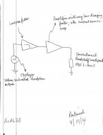
The attached image shows the diagram of the sound system which I used to assess the subjective influence on it by the Stereo Acoustic Absorber [SAcAb] described in the above posts. Here is its description.
1. The volume-controlled output of a SONY CD's headphone amp is first fed to a low-pass filter. I'll show its picture in the next post. I set its F3 at 180 Hz. The slope is undeclared by the manufacturer. Its sole purpose was to allow me to focus my hearing on the bass region with next to nil distraction from the complementary high pass portion. It so happened that low level vocals crept into the output and turned out to be beneficial for my subjective assessment.
2. The stereo output of the low pass filter was fed to a utility current source amp. This fulfilled the requisite amp with very low damping factor driving a conventional loudspeaker; as taught in text #1 of the Pass patent I wrote in the previous post.
3. ADS L300C is a conventional bookshelf loudspeaker; used which fulfilled the patent suggestion shown in text #2 of previous post. I sat the pair of L300Cs on the Bandpass Subwoofers which are the components assisting the Primary AcAb that I described earlier. The sound of this loudspeaker driven by a transconductance amp was poor. I will show a picture the set up in the next post.
3. The scope probes were put across the terminals of the microphone voice coil of the Primary AcAb so as to show the presence of standing waves as I listened to this type of muffled music. SAcBab was energized but its four switches were in the off positions at its amps' outputs.
4. I listened to different instrumentals, music with male and female vocalists. Each song was played 3-4 times back to back with SAcAb online and off line.
5. With SAcAb offline, bass had an onset, a propagation and a termination. With SAcAb online, the relative time to terminate the bass was shortened. The loudness of the bass with SACAb online was also diminished, but tighter and more detailed than with SAcAB off line. The prolonged time of bass termination with SAcAb off line was bass overhang; meaning the bass carried on till it naturally stopped. The higher bass loudness due to overhang sounded bigger and maybe was boom-like, but was artificial when compared to the tighter and more detailed bass with SAcAb on line.
6. The remnant male and female vocals output from the low pass filter were more intelligible and detailed with SAcAB on line than with it off line. Interestingly, and especially the vocals containing SSSS were clearer, and hissy.
7. The above led me to conclude that SAcAb online improved the performance of the conventional loudspeaker.
My observations did not fall in this trap of iffy thought; maybe/I am not sure that I heard this or that; but rather I am confident that I really heard this and that of the above.
There is a high probability that Mr. Pass did the same experiment like I described above; because he declared its sonic subjective results with clarity and detail to the patent examiner and to the world to read [texts #1 and 2 in previous post].
Best regards
Attachments
Pictures
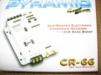
The attached picture on the left shows the commercial low-pass filter made by Pyramid which I used in the above study. It was made for automotive use but was readily adapted for home application by adding a regulated 12 V power supply [not shown].
1. The upper slider switch allowed the selection of F3 at 50, 90, or 180 Hz. I used F3 = 180 Hz in the experiment I discussed in the above post.
2. The left slider switch of the pair shown towards the left corner is on/off. It enabled a 12 dB bass boost at 45, 80, or 120 Hz; that can be selected by its companion right switch. I did not use this option; but I intend to try it at 80 Hz.
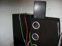
The attached right picture shows the conventional ADS L300C loudspeaker [played the bass-only music] sitting atop the Visonik bandpass subwoofer used in the Stereo Acoustic Absorber [SAcAb] setup to assist the Primary AcAb or [PAcAb].
1. The picture shows the Left corner. The DVC subwoofer of PAcAb sits smack in the corner. It is the primary sensor of standing waves.
2. The bandpass subwoofer assisting the performance of PAcAb sits next to it. Its four ports performed similarly; when SAcAb is online [low SPL] or off line [higher SPL].
3. ADS L300C sat above the top vent [by choice] and was angled towards me during listening of its muffled music.
4. The right corner had a similar setup which was a mirror image of that in the left corner.
5. The analog sound pressure meter behaved like an analog VU meter when playing this type of music. I noted sound pressure with SAcAB off line, and then noted it drop to lower values with SAcAb online. This performance was expected, and readily demonstrated.
Best regards
The attached picture on the left shows the commercial low-pass filter made by Pyramid which I used in the above study. It was made for automotive use but was readily adapted for home application by adding a regulated 12 V power supply [not shown].
1. The upper slider switch allowed the selection of F3 at 50, 90, or 180 Hz. I used F3 = 180 Hz in the experiment I discussed in the above post.
2. The left slider switch of the pair shown towards the left corner is on/off. It enabled a 12 dB bass boost at 45, 80, or 120 Hz; that can be selected by its companion right switch. I did not use this option; but I intend to try it at 80 Hz.
The attached right picture shows the conventional ADS L300C loudspeaker [played the bass-only music] sitting atop the Visonik bandpass subwoofer used in the Stereo Acoustic Absorber [SAcAb] setup to assist the Primary AcAb or [PAcAb].
1. The picture shows the Left corner. The DVC subwoofer of PAcAb sits smack in the corner. It is the primary sensor of standing waves.
2. The bandpass subwoofer assisting the performance of PAcAb sits next to it. Its four ports performed similarly; when SAcAb is online [low SPL] or off line [higher SPL].
3. ADS L300C sat above the top vent [by choice] and was angled towards me during listening of its muffled music.
4. The right corner had a similar setup which was a mirror image of that in the left corner.
5. The analog sound pressure meter behaved like an analog VU meter when playing this type of music. I noted sound pressure with SAcAB off line, and then noted it drop to lower values with SAcAb online. This performance was expected, and readily demonstrated.
Best regards
Attachments
I stimulate the music room with a 50 Hz signal to generate standing waves at the corners, I used a diy power CSA to drive a pair of 15 inch musical instruments which are bolted to the ceiling. They focus their output [like a stereo pair] towards a sweet spot/point where my ears go on the floor.
The above excerpt is from post #50. I described in it a stereo sound system which I like; because it is highly listenable. Please note the following:
1. I repeated the music listening study which I discussed in the above post by using the 15" musical instrument drivers [MID] instead of ADS L300C. The results of this experiment were the same as I found with L300C. But;
2. The vocals; male and female were more intelligible in this case than with L300C. Maybe due to the rising inductive impedance of the 15 " MID, which put out more acoustic power in this vocals' audio regime like others which are full range; when driven by a transconductance amp.
3. The vocals were relatively more intelligible with the Stereo Acoustic Absorber on line rather than off line. Actually, this cleaned-up music was very listenable, and surprisingly acceptable. It ..
4. Gave me a heads-up on the upcoming state of my hearing at 95 years old.
Conclusions:
1. The results todate will impact [favorably or improve ] the sound systems of DIYers who use amps of low [and high] output impedance driving all types of loudspeakers.
2. In general, a low pass filter as described earlier maybe used as a diagnostic tool which will allow the DIYer to assess the performance of the loudspeaker in this limited audio band; independent from the distraction of its high pass complement.
Best regards.
One thing led to..
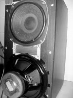
This unusual-looking full range loudspeaker, which I used to demonstrate the Pass invention. Here is a description of its moving parts.
1. The top driver is ~10 inches in diameter [made in Japan] which once was the woofer [8 Ohms] of an old Radio Shack 3-way loudspeaker. It plays the role of a full-range [FW] driver. It is driven by a very low damping factor current source amp.
2. The inverted driver is 12 inches in diameter, and has two 8 Ohms voice coils. It is mounted as shown because I could not fit it the formal way in a second opening like that of the top FW driver. It plays the role of an Acoustic Absorber [AcAb] per the general teaching of the Pass patent.
3. The two drivers share one acoustic suspension enclosure.
4. This loudspeaker is surprisingly listenable. I listened to it for several hours already, and loved its performance with the Pass invention enabled.
I'll post the schematic of AcAb, and explain further the working and performance of this loudspeaker.
Attachments
I was a bit tardy but..
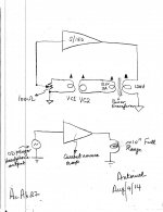
The following image shows the diagram/schematic of the system supporting the prototype loudspeaker of the previous post.
1. The bottom diagram pertains to the 10", and full range [FR] upper driver of the loudspeaker. It shows a simple signal train from CD player via a trans-conductance power amp source to music output. It was the source of my subjective comments below.
2. The top diagram pertains to the inverted 12" dual voice coil [DVC] subwoofer driver. It is simple, and was operated six different ways. The step-down power transformer, and the 100 Ohm pot manage the level of feedback [stability against oscillation], and protect the DVC sub from the direct wrath of an powerful oscillating amplifier.
3. I used a THRESHOLD S/150 amp in the assembly so as to derive clear results. Others usable.
4. Please note the relative phase of the electrical signals shown by the shaded triangles atop the "coils".
5. As shown [phase] in the upper diagram, the bass output of the loudspeaker was dramatically increased. It was deep, tight, and solid. If the face of the loudspeaker is like a wall adjacent to a room corner, then the DVC assembly was operating contrary to the teaching of the Pass patent of a loss in bass energy.
6. Next, the phase of only one electrical signal was reversed. The bass output of the loudspeaker was substantially diminished relative to that heard from the above point 5; conceptually like taught by the Pass patent; meaning cancellation of bass energy akin to the destruction of standing waves.
7. Next, the 100 Ohm volume control was operated from its set point towards its minimum during the operations described in the operation modes shown above in points 5 and 6. It behaved like a bass volume control. I will need to listen more so as to better describe the outcome in cases 5 and 6. But, the overall tonal balance of the loudspeaker was clearly affected .
8. The fifth mode of operation fully minimized the 100 Ohm "bass control" pot; meaning the input of S/150 is shorted to ground. I will need to understand its influence on sound. And possibly use this state as a reference because negative or positive feedback around S/150 will be absent.
9. The sixth mode of operation disconnected the power output of S/150 to the step down power transformer.
10. The music from all modes of operation sounded damn good. I was surprised by the music quality from the sixth mode of operation.
Best regards
Attachments
Summary
In bullet format in several short posts:
1. The best DIY of this patent can only be the device which Mr. Pass described in it.
2. DIYer has the opportunity to practice the patent quickly by assembling commercially enclosed subwoofers, and power amplifiers.
3. The thread was/is educational to me. The practical facet of this DIY began with post #51; with assemblies that suppressed.
standing waves successfully.
4. The assembly which utilized an Electret microphone worked like that shown in the patent, and is highly recommended to DIY.
5. The assembly which utilized a DVC subwoofer [one coil as microphone and the other for loudspeaker] was also successful. Its performance was different from that using Electret microphone .
Summary contd..
Posts# 63 and forward, show the DIY which utilized an enclosed DVC subwoofer, as a stand-alone Acoustic Absorber. One voice coil operated as microphone, and its independent mate as the loudspeaker. But;
1. It had a mediocre performance for diminishing the sound pressure of standing waves [SWs]. This baffled me for a long time.
2. This solo DVC subwoofer was later assisted by a second enclosed subwoofer [bandpass, sat next to it] so as to help it reduce the sound pressure of SWs in a substantial [measurable] way.
3. The DVC subwoofer assembly [included a dedicated amp, level control and power transformer] generated an electrical signal representing SWs, which was then fed to another stand-alone amplifier that drove the assist subwoofer. This approach worked quite well but;
4. Who else has a collection of subwoofers, and the floor space to accommodate these big boxes? This led me to ask..
5. What if I had only one enclosure to house both a DVC driver [so as to fulfill the patent teaching], and another independent single voice coil woofer to "assist" it?
6. These two independent drivers may reside in separate or share the same internal acoustic suspension spaces.
7. Post #72 showed a loudspeaker whereby the two drivers shared the same internal enclosure. I explained its unusual looks. It sits in the left corner and is asked to deliver the value attendant to point #5.
8. Will it? It follows that I must show that it belongs in this thread, instead of a DIY loudspeaker of another thread.
Notes
I pursued; but failed to achieve the objective [of point #5] in post #76. The assembly of components [those shown in post #73] was deceptively simple; but ineffective, and this approach [common enclosure] was abandoned.
There is a salvage value attendant to the assembly shown and well-described in post #73. Here are new results and observations for it [please note phase relations]:
1. The step down transformer was omitted from the assembly using S/150 power amp. Assembly was stable against oscillation.
2. Curious observation: Minimize 100 Ohm volume control at input of S/150 and across VC1. Disconnect the power output of S/150 to VC2 [unplug banana plug] . Energize the single coil woofer with a tone signal to get ~74 dB SPL in left corner. Now connect power output of S/150 to VC2. SPL decreases 2-4 dB; depending on frequency. Note that the voltage drive across the speaking woofer was not perturbed before and after connecting VC2 to S/150. Advance the 100 Ohm volume control towards maximum. SPL increased back to 74 dB at some point and finally peaked at ~80 dB at max volume.
3. The speaking woofer was energized with the SONY integrated amp described previously. This woofer and an external 2-way satellite loudspeaker [A/D/S L-300 C] were connected as a 3-way full-range loudspeaker. Awesome bass, and well defined balance of spectrum.
Please Go back to the assembly of post #73, and do following:
1. Put step down transformer at the input of S/150 instead of at its output . The output of VC1 [microphone] was stepped down [divide voltage by 9] and the secondary winding of transformer loaded with the 100 Ohm volume control feeding the input of S/150
2. Minimize this 100 Ohm volume control; because this new assembly can oscillate at a certain volume setting setting.
3. Reverse one phase connection of those shown in the assembly of S/150
4. Advance volume control [~1/2 max] for onset of shriek oscillation. Mark this set point.
5. Minimize vol control.
6. Repeat the steps mentioned earlier with the SPL measurements. Got similar behavior; except SPL in the corner decreased another 2-4-dB as the vol control was increased to the set point of shriek oscillation.
7. Assembled the 3-way loudspeaker with L300 C. Diminished bass by comparison to previous case.
I will be glad to answer questions, do suggested experiments [of your choice] while this system and its components are in place.
Best regards.
Thank you Antoinel for the detailed posts, and to Mr. Pass for his inputs.
I am now researching active bass traps for DIY.
My question is, does anyone know what Bag End do differently in their "E-trap"?:
Bag End E-Trap
Has anyone found their patent #?
I am now researching active bass traps for DIY.
My question is, does anyone know what Bag End do differently in their "E-trap"?:
Bag End E-Trap
Has anyone found their patent #?

Thank you Antoinel for the detailed posts, and to Mr. Pass for his inputs.
I am now researching active bass traps for DIY.
My question is, does anyone know what Bag End do differently in their "E-trap"?:
Bag End E-Trap
Has anyone found their patent #?
The name of this supplier is Modular Sound Systems, Inc. My quick search of it in uspto as Assignee gave 0 patents and 0 applications. It has licensed tech from others [for example Long/Wickersham Labs] which may have the rights to a possible patent. An E-trap product is absent from their Home line of products; where it belongs. Fortunately, its front webpage has a heading E-Mail-Contact Us.
N.B. US 6,795,557 B1 [Makivirta et al] was granted on Sep. 21, 2004 and discusses the issue. It was provided in an earlier post of this thread.
Best regards
- Home
- Amplifiers
- Pass Labs
- DIY the device of US Patent 4,899,387