Bag End patent #
Just to add to this thread, for posterity:
The above patent # 6,795,557 appears to be a system that doesn't use feedback. The Bag End E-trap uses feedback. I found this AES paper presented by Bag End:
http://www.bagend.com/site/wp-content/uploads/2015/03/AES-E-Trap-Paper.pdf
It mentions a patent pending by the author A R Kashani.
Doing a patent search I found patent # US7190796 B1
https://www.google.com/patents/US7190796
"Active feedback-controlled bass coloration abatement"
Interestingly it doesn't reference Nelson Pass's patent.
A quick scan shows me the E-Trap adds a pair of parametric EQ's to Pass' original idea, ostensibly for addressing the 2 worst modes.
The only advantage I can think is that it targets your 2 worst modes, and doesn't diminish the "room gain" of other frequencies (thus not increasing subwoofer SPL output capability)... perhaps having some reverberation with a short RT60 (at these other frequencies), is OK.
Here's a short review of it
Music in the Round #31 Page 2 | Stereophile.com
BTW here's a cool set of bass articulation test tones mentioned in the paper:
| Acoustic Sciences Corporation
Hello everyone,
I am following an educating thread by DIYer jlo which is entitled Acoustics of corners in the Multi-Way Forum. Post#118 gave a reference to an AVAA system by PSI Audio at PSI Audio - Swiss Precision Audio - Accurate Loudspeakers and bass trap. AAVA stands for Low Frequency Active Velocity Acoustic Absorber. It sits and performs in the corner(s) of the listening room. Roger Roschnik of PSI Audio presented four videos about this technology which are highly recommended to view as they are educational and describe the technology. One important video of a ~23-minute presentation at a conference is embedded in a shorter one shown at the top right of the web page. Roger spoke also of patents for this technology. I hope to find them.
Best
Anton
As a sort of tangent to this thread, The Woofer Tester Pro has a feature that allows any two of the inputs and/or output curves to be divided in real time.
You can use this feature on the two (L and R) mic inputs. If you place one mic in front of a closed box woofer and then hold the other mic in your hand, you can walk around a room and the resulting plot of the divided curves is the transfer function of the room at the point of the microphone in your hand.
You can manually map the modes of your room. You can place traps and then see if the traps reduce or eliminate the mode.
I used this setup to prove to a sound board operator that his choice of where to place his sound board was at a strong room mode that made the bass guitar amp on stage sound much louder to him than what the audience was hearing.
As Lord Kelvin said, "If you can measure a thing, and express it in numbers, you can claim to know something about it."
If I understand you endeavor in this thread, you are trying to reduce the "boom" of a room which are due to the geometry of the room.
One way to tame the boom is to find the mode(s), characterize them and then treat the room, then re-measure to see if you succeeded.
To accomplish this, you have to find each mode and measure its magnitude.
If you can simultaneously measure the spectrum of the output of a driven speaker and the spectrum of a different point in the room and divide the room point spectrum by the woofer spectrum, the result is the transfer function of the room at that point.
You can do this crudely by playing music with heavy bass and walk around every square inch of room. You can hear the boom against the walls and particularly in the corners.
When you divide the curves at a room mode location, you will see a peak rising above all of the other frequencies.
The simplest and cheapest way to reduce the mode is to stack up some rolls of owens corning fiberglass insulation at the room mode locaiton. The downside is that the solution is ugly, itchy and consumes valuable real estate.
I do not have saved curves to show. I only did the analysis once as a freebie favor in a large room where there was a stage at the front of the room and the sound mixer was against the rear wall. The mixer operator complained often about how loud the bass guitar was compared to the rest of the band. The blend of the bass guitar was only a problem at the rear wall. In the middle of the room, the balance was fine. I was able to show graphically what was obvious just walking around the room.
Listening application of a DIY DEF amp.
This post is the application part of the DEF power amp which I have already mentioned in post #291 of The DEF thread by Mr. Pass. I'll cut to the chase and describe:
1. The listening [unfinished] room in the basement of the home. It is 20 feet by 20 feet by 13 feet high. The diagonal on the floor is ~28 feet [corner to corner] and corresponds to one 40 Hz cycle. This 40 Hz is [per the Pass patent ] the gravest of these resonances [meaning standing waves]. This hobby room has useful clutter fill which is most probably beneficial for scattering sound.
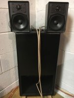
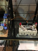
2. A picture of the application loudspeaker is attached. This loudspeaker system sits in a corner. The big box is a Dual Voice Coil subwoofer once supplied by MCM Electronics. The diameter of the driver is 10 inches. It fires at the floor at a 45 degree angle towards the opposing corner[28 feet away]. There is a dual two-way crossover inside its box. Its spec are unknown but can be measured. Each 8 Ohm voice coil and its high pass section are independent from the other. The satellites are 4 Ohm A/D/S/ L300.
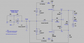
3. The attached schematic is for the power amp using DEF wired in common gate configuration. This style amp has informative background posts in the DEF thread. I'll show pictures of the Voltage Source and the DEF Common Gate amps in the next post.
This post is the application part of the DEF power amp which I have already mentioned in post #291 of The DEF thread by Mr. Pass. I'll cut to the chase and describe:
1. The listening [unfinished] room in the basement of the home. It is 20 feet by 20 feet by 13 feet high. The diagonal on the floor is ~28 feet [corner to corner] and corresponds to one 40 Hz cycle. This 40 Hz is [per the Pass patent ] the gravest of these resonances [meaning standing waves]. This hobby room has useful clutter fill which is most probably beneficial for scattering sound.
2. A picture of the application loudspeaker is attached. This loudspeaker system sits in a corner. The big box is a Dual Voice Coil subwoofer once supplied by MCM Electronics. The diameter of the driver is 10 inches. It fires at the floor at a 45 degree angle towards the opposing corner[28 feet away]. There is a dual two-way crossover inside its box. Its spec are unknown but can be measured. Each 8 Ohm voice coil and its high pass section are independent from the other. The satellites are 4 Ohm A/D/S/ L300.
3. The attached schematic is for the power amp using DEF wired in common gate configuration. This style amp has informative background posts in the DEF thread. I'll show pictures of the Voltage Source and the DEF Common Gate amps in the next post.
Attachments
The prototype power amp
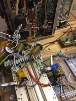
This post shows and describes the Voltage Source Amp [VSA] and the DEF amp [DEFcg] which are in the attached and same schematic I showed in the previous post.
1. DEFcG is shown in the far left view. The FETs are clamped down on the tunnel heat sinks. A fan in the back of this heat sink moves air through it and out. The plastic pill containers house PSU electrolytic caps, fuses, etc. The +/-V PSU of a spent radio receiver [back of the picture] powers DEFcg. The AC voltage on its power cord goes to a variac which then adjusts the rail voltages to DEFcg. The bias to the FETS [Vgs] is always turned on before the power rail voltages are introduced and increased.
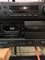
2. The power amp inside the pictured SONY MHC 1750 is the VSA. Its stereo power amp is built around an STK 412-770E thick film/hybrid chip. Its power rail voltages are +/-30 Vdc. I augmented its internal PSU's storage capacity with 2 external storage banks of electrolytic caps which are shown in the right view. The value of the external caps per rail is 0.05 Farad. The caps are slowly charged up through a 5 W/125 Vac light bulb [cold R ~280 Ohms] by using the SONY's PSU via a 3 conductor red cord. After 5 minutes, the 2 terminals of each light bulb are manually shunted/shorted across so as to expose the full capacity of the caps to the STK 412 power amp. This action is quite effective because I'm dealing with some mean bass energy in the listening room.
The loudspeaker system from the previous post is connected as shown in the schematic. The VSA and DEFcg are independently turned on while joined as in the schematic. SONY has a mechanical relay in series with its music power output which is enabled by switch [top left of unit called standby] and is a great precautionary feature.
The overall special power amp [OPA = VSA + DEFcg] is stable.
Notes
1. In any study, one needs a control amp for acoustic comparison. The L and R channels in SONY are the controls. One channel drives one coil of the subwoofer, and the second channel drives the second coil. The music input signal [Vin] to both SONY amps must be the same/identical. So, one gets a reference sound.
2. By contrast, OPA is the test amp. Its sound in the same loudspeaker system is the subject of comparison with that of the control.
to be continued..
This post shows and describes the Voltage Source Amp [VSA] and the DEF amp [DEFcg] which are in the attached and same schematic I showed in the previous post.
1. DEFcG is shown in the far left view. The FETs are clamped down on the tunnel heat sinks. A fan in the back of this heat sink moves air through it and out. The plastic pill containers house PSU electrolytic caps, fuses, etc. The +/-V PSU of a spent radio receiver [back of the picture] powers DEFcg. The AC voltage on its power cord goes to a variac which then adjusts the rail voltages to DEFcg. The bias to the FETS [Vgs] is always turned on before the power rail voltages are introduced and increased.
2. The power amp inside the pictured SONY MHC 1750 is the VSA. Its stereo power amp is built around an STK 412-770E thick film/hybrid chip. Its power rail voltages are +/-30 Vdc. I augmented its internal PSU's storage capacity with 2 external storage banks of electrolytic caps which are shown in the right view. The value of the external caps per rail is 0.05 Farad. The caps are slowly charged up through a 5 W/125 Vac light bulb [cold R ~280 Ohms] by using the SONY's PSU via a 3 conductor red cord. After 5 minutes, the 2 terminals of each light bulb are manually shunted/shorted across so as to expose the full capacity of the caps to the STK 412 power amp. This action is quite effective because I'm dealing with some mean bass energy in the listening room.
The loudspeaker system from the previous post is connected as shown in the schematic. The VSA and DEFcg are independently turned on while joined as in the schematic. SONY has a mechanical relay in series with its music power output which is enabled by switch [top left of unit called standby] and is a great precautionary feature.
The overall special power amp [OPA = VSA + DEFcg] is stable.
Notes
1. In any study, one needs a control amp for acoustic comparison. The L and R channels in SONY are the controls. One channel drives one coil of the subwoofer, and the second channel drives the second coil. The music input signal [Vin] to both SONY amps must be the same/identical. So, one gets a reference sound.
2. By contrast, OPA is the test amp. Its sound in the same loudspeaker system is the subject of comparison with that of the control.
to be continued..
Attachments

Two important details
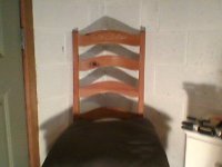
1. My listening position in the room which I have already described. It is in/at the corner opposite to the loudspeaker system which is 28 feet away along the floor diagonal. Any room corner is already known to be acoustically filthy. So, this listening application is an acid test to my subjective experiments which have an objective to determine the acoustic value of the sound system. I have a pic of the chair in the corner. I can also sit/squat on the floor in the same corner, and I can lay down with my head close to the onset of the Cartesian coordinates of this corner [loosely the epicenter of the acoustic filth].
2. The music source [Vin] is the headphone output of a SONY CDP-515 CD player. I use the R channel, and its volume is controlled remotely.
Here are the 2 important perceptions from auditioning music [played in mono] as described:
1. Music played by using the Control Amps in SONY MHC 1750 [described in the previous post] was not a satisfying experience [could be torture]. The bass was deep, mushy, and heavy. Tiresome.
2. Music played by using the Test Amp [OPA from the previous post] was a very satisfying experience. The bass of this sound system was deep, detailed, and tight. The performance of the satellite speakers was brilliant. Something good is going on; because I'd sit for 1 hour plus during several tests and enjoyed the resultant immense and alive-like sound.
Why? I have a plausible explanation which I'll post next.
Attachments
It appears that this sound system behaves like the device described in the Pass patent under study. It cleanses the room from resonances, and/or removes some bass energy from it . Here's a plausible explanation for the time being. Please refer to the attached and same schematic.
1. Let the voltage source amp [VSA] energize coil #1 so as to enable the woofer cone to [say] move out or travel towards me.
2. DEFcg is a current bootstrap. It simultaneously reacts by fully energizing coil #2. Thus it helps VSA to push the same cone out; because the currents through both coils, and the two coils are in phase.
3. Here's the important connection. A slight vacuum from a standing wave in front of the cone can also pull/move it out towards me. Thus, coil# 1 [and/or #2] become a microphone with a current flowing through it. This simultaneously causes the DEFcg current bootstrap to inject a similar current in coil #2, and thus help/move the cone out. This resultant forward motion of the woofer generates a slight positive pressure which minimizes or wipes out [meaning counteracts] the vacuum as taught by the Pass patent. Essentially absorbing the standing wave per this invention.
4. Let the VSA energize coil # 1 so as to enable the woofer cone to move back or away from me.
5. The resultant reaction of DEFcg current bootstrap is to help the cone continue to move back; meaning in the same direction which was initiated by VSA.
6. Here is the second important connection. A slight pressure at the face of the woofer from a standing wave pushes it back or away from me. The cone and its coils become a microphone. The consequent current bootstrap action of DEFcg pulls the cone back; meaning it keeps it moving in the same direction away from me. This motion of the cone creates a slight vacuum which minimizes or wipes [counteracts] the slight positive pressure from the standing wave and/or resonance. Thus absorbing the standing wave and/or resonances as taught by Pass in his patent.
7. Here is a third important connection. The resonances above are clearly external to the woofer cone from standing waves in the room. But; they might as well be inside the box housing it. This suggests that the combined operation of the loudspeaker [as box microphone too] and the Overall Power Amp [OPA; special!] cleanse/improve the performance of the loudspeaker itself.
Notes left over from previous posts:
1. I am a Bass Trap when I sit in the corner and listen to music. My muscles, some adipose tissues, and the garments I wear are naturally absorbing of base energy. Push comes to shove I may even consider cloaking myself with additional approved bass trap materials to augment the performance of " yours truly" bass trap. I'd say I'll be one funny sight to behold, but absolutely no itchy fiberglass stuff!
2. An error on my part. The longest dimension in my test room is the diagonal from a ceiling corner to the opposite floor corner, and not that on the floor only. The new wavelength of the most offending room resonance [per Pass patent] is ~36 Hz instead of 40 Hz.
Are you ready for a stereo system?
Best
Anton
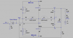
The prototype amp/loudspeaker system which I listened to and mentioned in the previous post was modified and improved. The new schematic is attached. Additional info is found in the last two posts of the "DEF" thread. Please note the following relevant changes:
1. The location and circuit arrangement of the encircled two voice coils 1 and 2 of the dual voice coil [DVC] subwoofer. The indicated relative phase of the voice coils enables Positive Feedback. Positive feedback is preferred in this application
2. The previous voltage source amp [VSA] which has a possible voltage gain = 21 X [say that of SONY MHC 1750 amp] was replaced with a power buffer/follower [see post in DEF thread].
3. The bias or current idle of the FETs was increased to +/-0.6A. The ideal and future bias will best be at ~+/-1.3 A at +/- 23 Vdc . Because it is the primary source of power to the load.
4. The power buffer/follower delivers a small amount of music power to the voice coil #1 of the subwoofer and thus to its satellite loudspeaker. Little output emanates from this satellite loudspeaker. Consequently, this satellite loudspeaker can be replaced with an 8 Ohm non-inductive power resistor [so as to load the internal high pass crossover network]; but without an effect on sound.
What has not changed?
1. The loudspeaker system is the same and is in the same corner of the room.
2. My listening position is in the opposite corner along the floor diagonal [~28 feet away].
Subjective observations:
1. The bass is thunderous, clean and tight.
2. The rest of the audio spectrum is highly detailed. Vocals are intelligible and crystal clear.
3. Could not detect standing waves by walking towards the walls of the room.
4. Listening to this system for an hour+ was a satisfying experience. And that is my objective
5. This music system is stable against oscillation; provided the power buffer to its input is connected [see the last 2 posts in the DEF thread].
More to post on absorbing acoustic trash in the listening room...
Best
Anton
1. Let the voltage source amp [VSA] energize coil #1 so as to enable the woofer cone to [say] move out or travel towards me.
2. DEFcg is a current bootstrap. It simultaneously reacts by fully energizing coil #2. Thus it helps VSA to push the same cone out; because the currents through both coils, and the two coils are in phase.
3. Here's the important connection. A slight vacuum from a standing wave in front of the cone can also pull/move it out towards me. Thus, coil# 1 [and/or #2] become a microphone with a current flowing through it. This simultaneously causes the DEFcg current bootstrap to inject a similar current in coil #2, and thus help/move the cone out. This resultant forward motion of the woofer generates a slight positive pressure which minimizes or wipes out [meaning counteracts] the vacuum as taught by the Pass patent. Essentially absorbing the standing wave per this invention.
4. Let the VSA energize coil # 1 so as to enable the woofer cone to move back or away from me.
5. The resultant reaction of DEFcg current bootstrap is to help the cone continue to move back; meaning in the same direction which was initiated by VSA.
6. Here is the second important connection. A slight pressure at the face of the woofer from a standing wave pushes it back or away from me. The cone and its coils become a microphone. The consequent current bootstrap action of DEFcg pulls the cone back; meaning it keeps it moving in the same direction away from me. This motion of the cone creates a slight vacuum which minimizes or wipes [counteracts] the slight positive pressure from the standing wave and/or resonance. Thus absorbing the standing wave and/or resonances as taught by Pass in his patent.
7. Here is a third important connection. The resonances above are clearly external to the woofer cone from standing waves in the room. But; they might as well be inside the box housing it. This suggests that the combined operation of the loudspeaker [as box microphone too] and the Overall Power Amp [OPA; special!] cleanse/improve the performance of the loudspeaker itself.
Notes left over from previous posts:
1. I am a Bass Trap when I sit in the corner and listen to music. My muscles, some adipose tissues, and the garments I wear are naturally absorbing of base energy. Push comes to shove I may even consider cloaking myself with additional approved bass trap materials to augment the performance of " yours truly" bass trap. I'd say I'll be one funny sight to behold, but absolutely no itchy fiberglass stuff!
2. An error on my part. The longest dimension in my test room is the diagonal from a ceiling corner to the opposite floor corner, and not that on the floor only. The new wavelength of the most offending room resonance [per Pass patent] is ~36 Hz instead of 40 Hz.
Are you ready for a stereo system?
Best
Anton
The prototype amp/loudspeaker system which I listened to and mentioned in the previous post was modified and improved. The new schematic is attached. Additional info is found in the last two posts of the "DEF" thread. Please note the following relevant changes:
1. The location and circuit arrangement of the encircled two voice coils 1 and 2 of the dual voice coil [DVC] subwoofer. The indicated relative phase of the voice coils enables Positive Feedback. Positive feedback is preferred in this application
2. The previous voltage source amp [VSA] which has a possible voltage gain = 21 X [say that of SONY MHC 1750 amp] was replaced with a power buffer/follower [see post in DEF thread].
3. The bias or current idle of the FETs was increased to +/-0.6A. The ideal and future bias will best be at ~+/-1.3 A at +/- 23 Vdc . Because it is the primary source of power to the load.
4. The power buffer/follower delivers a small amount of music power to the voice coil #1 of the subwoofer and thus to its satellite loudspeaker. Little output emanates from this satellite loudspeaker. Consequently, this satellite loudspeaker can be replaced with an 8 Ohm non-inductive power resistor [so as to load the internal high pass crossover network]; but without an effect on sound.
What has not changed?
1. The loudspeaker system is the same and is in the same corner of the room.
2. My listening position is in the opposite corner along the floor diagonal [~28 feet away].
Subjective observations:
1. The bass is thunderous, clean and tight.
2. The rest of the audio spectrum is highly detailed. Vocals are intelligible and crystal clear.
3. Could not detect standing waves by walking towards the walls of the room.
4. Listening to this system for an hour+ was a satisfying experience. And that is my objective
5. This music system is stable against oscillation; provided the power buffer to its input is connected [see the last 2 posts in the DEF thread].
More to post on absorbing acoustic trash in the listening room...
Best
Anton
Attachments

Awesome, not being a native speaker nor trained in electronics it will take me some time to fully understand what is going on and build some of those myself (It would be great to know some parts that work well and are not too expensive). Until then I am using a dsp with an electret mic but I highly appreciate your work and that you share all those information. Best regards from Hamburg
Awesome, not being a native speaker nor trained in electronics it will take me some time to fully understand what is going on and build some of those myself (It would be great to know some parts that work well and are not too expensive). Until then I am using a dsp with an electret mic but I highly appreciate your work and that you share all those information. Best regards from Hamburg
Thanks for showing me this thread!
Amazing design!
..... but I'm afraid I'm going to join oreo382 under the blanket of dumbness

Thank you yentzee and oreo382 for your posts. I hope that you experiment with this set up. One's ears are the final and sole judge..
While I trust my ears to some extent, I trust a propper REW before/after meassurement even more.
Some day I might even build this one here and then I will surely post some of the meassurements here.
Hello Schlumpfpeter and thanks for your post. Mr. Pass [and others] do encourage DIYers to experiment and to test [personal] or their hypotheses. How else can I unravel possible sonic/subjective improvements? I continue to experiment with the subject matter. IMHO, minimizing standing waves [SW] and their impact in my listening room is the last frontier to conquer; but with an additional enhancement. I hope that you and others:
1. Had the opportunity to experiment with the remarkable DEF circuit of Mr. Pass. A gem!
2. Noted in my posts the suggested and evolved hypothesis to use any loudspeaker in the corner of the listening room so as to enable it to do double duty [like a bat]. Send high fidelity music to my ears and simultaneously "suppress" the returning [SW] echoes. This approach will also free space in the room for "dancing" from absent expensive loudspeakers which can be toppled over as lovers sway back and fro.!
Best wishes
Anton
That is indeed, a very interesting idea, to use the speaker itself for the cancelation of the standing waves. Only thing which comes to my mind is that you would need to have a speaker using a double coiled subwoofer. I don't think that those special SWs are that common, at least I haven't seen one.
Is this schematic specifically designed to work with a dual coil speaker and the amp you mentioned or would it be possible to use this schematic but instead use any amplifier and get the "modulating" signal from an electret sitting in front of the sub, and feeding the signal after preamp into the circuit where the coil from the sub is located?
I really would love to try but don't really want to buy lots of stuff. Would be great if I could use my adam audio sub 7 for this with a small electret mic or use any subwoofer fed by a cheap wondom class d amp.
I really would love to try but don't really want to buy lots of stuff. Would be great if I could use my adam audio sub 7 for this with a small electret mic or use any subwoofer fed by a cheap wondom class d amp.
- Status
- This old topic is closed. If you want to reopen this topic, contact a moderator using the "Report Post" button.
- Home
- Amplifiers
- Pass Labs
- DIY the device of US Patent 4,899,387