That will not work properly because the two primary windings are seeing different voltages across them and will "fight" each other. Assume that the feedback node has voltage Vfb. The voltage across the upper primary is In+ - Vfb. The voltage across the lower primary is Vfb - In-.
If In- = - In+, then clearly the voltages across the windings are different unless Vfb=0.
If we believe that the total flux in the transformer is the sum of the contributions of the two primary windings, then the total flux will be proportional to (In+ - Vfb) + (Vfb - In-) = In+ - In- and the feedback has no effect.
coffee is brewing , now ... so take this with grain of salt
Mr. Pass and Mr. Zen Mod. Is there a transformer which will present a 20 KHz bandwidth in OLG F6, and will it improve performance of CLG F6?. The OLG F6 circuit is a specific and useful test method to find such a transformer. Plot OLG versus Frequency for each TUT.I can't give you exact recipe , not having experience with exact Jensen type ;
whatever - speaking strictly of xformer - loading each secondary with nominal impedance (150R) will result in better bandwidth
be aware that Jensen guys made it exactly that way
don't think even for a sec that Pa doesn't know that - he just took different approach - to correct entire amplifier , killin' seven flies with one blow
1938 - Mickey Mouse, Minnie Mouse - The Brave Little Tailor - YouTube
Thank you Mr. Pass. I'll read it slowly and carefully on your FW site. I have the weakness of speed reading.No doubt there is such, but you are likely to find that some other parameter
has been traded for it.
Did you read the transcript of the BAF talk on the F6?

N.B. Got the point. The Jensen in F6 is already a rarity per its writeup. Others which may push a higher OLG bandwidth will be unobtainium and prohibitively expensive.
Last edited:
Thanks Zen Mod. I also found it on the FW site. I will have to read it many more times to absorb it and fully appreciate its content. It is a very well written seminar/article. The writing style of Mr. Pass like his past articles flowed smoothly, was clear, and he loaded it with valuable present and future information. As written, it is a technical feast for the mind of DIYers.
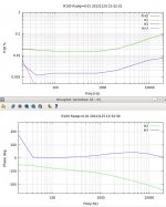
The transformer coupling in the F6 feedback loop cause the phase of the 2nd harmonic to vary with frequency. Here are THD vs Freq and Phase vs. Freq plots for the F6 and the F5. Not how much greater the phase shift is for the F6, particularly in the mid frequencies.
I suspect that this changes the sonic signature of the amplifier.
I suspect that this changes the sonic signature of the amplifier.
Attachments
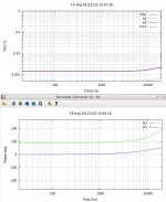
In my previous post, the F5 THD was so low that the phase change was totally determined by the MOSFET gate capacitances.
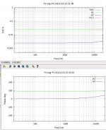
Here is the same F5 circuit with P3 adjusted for 0.025% 2nd harmonic. As you can see, the phase is essentially constant to 20kHz.
Here is the same F5 circuit with P3 adjusted for 0.025% 2nd harmonic. As you can see, the phase is essentially constant to 20kHz.
Attachments
It would be hard to adjust the F5 to have 3rd harmonic high enough or
to have the H2/H3 vs frequency at all similar to the F6.
What would be interesting is to see H2, H3 plots with phase for some vacuum tube amps with sonic signatures that are at all similar to the F6.
to have the H2/H3 vs frequency at all similar to the F6.
What would be interesting is to see H2, H3 plots with phase for some vacuum tube amps with sonic signatures that are at all similar to the F6.
Interesting thing would be to listen to both circuits adjusted for similar harmonic structure and see if they sound the same.
What I was really interested in with these curves was the variation of phase of H2 vs. frequency. Nelson has talked about having a positive (expansion) or negative (compression) phase relation between the H2 and H1, but this relationship is obviously non-constant for the F6, even over the range from 100Hz to 5000Hz, where there is about 100 degrees phase change.
I meant in general ratio, not 100% matching. At the very least, it would tell you the importance of having it flat across frequency. In reality, things start to become background above 8K-10k
I find your choice of a triode amp for study by lhquam to be interesting. I have speculated in earlier posts that loop feedback in F6 reorganized its intrinsic OLG pentode charateristic curves to triode-like ones; by analogy with Schade Feedback in vacuum tube circuits. OLG F6 is a voltage controlled [modulated] current source which has published pentode characterisics for its output stage JFETs and also for the future diyF6 with output MOSFETs. The question which hangs or put this way: how does one prove whether CLG F6 has been transformed to a voltage controlled resistor like a triode and/or its amp?If I had a 300B amp, I would mail it to lhquam asap. That was very interesting! Thanks.
I think the relative amplitude and phase of harmonics is what imparts a characteristic sound. You may be on to something here.
Last edited:
nelson, The distinction between the F6 op stage and almost every other quasi-comp is pretty apparent but what about f6 vs circs ?
ie what advantage(s) would you reckon between this topology and a transformer input circlotron ? (other than the need for two supplies for the latter I mean.)
ie what advantage(s) would you reckon between this topology and a transformer input circlotron ? (other than the need for two supplies for the latter I mean.)
Listening session notes
I had a nice listening session tonight and I have never heard another amplifier that reveled absolute phase better. I would go so far as to say that it becomes almost distracting. I would normally just put on something to listen to and go, now I need to test the absolute phase because it is so obvious when it is wrong when I start to listen. I also came across an album that it changes track to track, amazing. Even my SET amps don't reveal it this well. The F6 is truly a special amp.
I had a nice listening session tonight and I have never heard another amplifier that reveled absolute phase better. I would go so far as to say that it becomes almost distracting. I would normally just put on something to listen to and go, now I need to test the absolute phase because it is so obvious when it is wrong when I start to listen. I also came across an album that it changes track to track, amazing. Even my SET amps don't reveal it this well. The F6 is truly a special amp.
Update
I degenerated the output R100s on my F6 by adding the .1ohm resistor and 10 ohm pot. I need to do more listening but for me:
With each pot turned to get min wiper to source resistance (.3 ohms) I seemed to get widest soundstage, good depth and nice attack
Keeping the Q1 pots at .3 ohms and increasing the Q2 pots so that wiper to source was 1 ohm I seemed to have the best bass and nice detail
The opposite settings was also true Q1 pots at 1 ohm and Q2 pots at .3 gave very nice bass and nice detail
Don't quite understand that but I want to do some extended listening
Question - have others used all four pots/resistors at once or may it be better to use them on Q1 with Q2 at 0 ohms (no pot/resistor) or alternately Q2 with pot and Q1 with no resistor?
Just going my ear right now - seem to be able to duplicate with just resistance measurements.
Thanks and best
Bob
- Home
- Amplifiers
- Pass Labs
- F6 Amplifier