And I guess sticking the pot right after the buffer and before the entrance of the transformer makes no sense... That s the reason why Papa added the buffer there in the first place...
So if we go with simplicity, a plain pot in the entrance would be the reasonable choice... at least for me... My sources are low impedance anyway. It's the volume control requirement that messes things up...
So if we go with simplicity, a plain pot in the entrance would be the reasonable choice... at least for me... My sources are low impedance anyway. It's the volume control requirement that messes things up...
Last edited:
There's probably no free ride here. Only what does the least damage.
Damn you....

From that point of view, the gain from impedance matching should be bigger that the impact from the extra jfet buffer in sound...
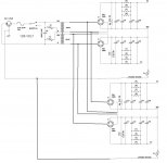
There was a discussion here about PSU layout in F6 paper: separate two channels even in stereo configuration. Can I use two separate capacitor blocks(like in dual mono), but one transformer and two bridges? Will it better than just one old F5-style PSU configuration? I have two store PSU boards, but one transformer. I was thinking what can I do with it to get closer to what Nelson proposed...
This one is Primrose. Only if I drop in Antek as the second, which I think is not good
I think Antek is just fine.
I use them in most of my builds.
I always go up a notch or two in amp rating, the pricing allows me to do that compared to Plitron which I have also used. Don't know about Primrose.
Rush
There was a discussion here about PSU layout in F6 paper: separate two channels even in stereo configuration. Can I use two separate capacitor blocks(like in dual mono), but one transformer and two bridges? Will it better than just one old F5-style PSU configuration? I have two store PSU boards, but one transformer. I was thinking what can I do with it to get closer to what Nelson proposed...
use separate Graetz bridges for each C bank
so , if you're using one bridge config , you'll need two - each C bank having one ....... while center tap from xformer will be common gnd point for both channels
if you're using two bridges config ( as in Pa's latest FW amps ) , then each C bank will have own two bridges and own isolated gnd point ...... (needing sum of 2+2 bridges for amp )

Thanks! That's what I was thinking about but for some reason decided that it is too simple to be correct .
Btw, where is our respectful German friend who compared a F5-type PSU with new a F-6-type, is it really so much bette? Will two separate cap banks be almost as good as two mono PSU in terms of those HF noise?
ZM, I looked into your blog about sonido, looks good. Still have hard time to decide on AlNiCo vs not always was dreaming of alnico, but curves look flatter with ferrite magnets
.Btw, where is our respectful German friend who compared a F5-type PSU with new a F-6-type, is it really so much bette? Will two separate cap banks be almost as good as two mono PSU in terms of those HF noise?
ZM, I looked into your blog about sonido, looks good. Still have hard time to decide on AlNiCo vs not
always was dreaming of alnico, but curves look flatter with ferrite magnets Thanks! That's what I was thinking about but for some reason decided that it is too simple to be correct
Btw, where is our respectful German friend who compared a F5-type PSU with new a F-6-type, is it really so much bette? Will two separate cap banks be almost as good as two mono PSU in terms of those HF noise?
......
never , really ; it's not just HF noise , but also hum wise and stereo separation
.....
ZM, I looked into your blog about sonido, looks good. Still have hard time to decide on AlNiCo vs not
my ears were satisfied with every iteration - be it alnico or ceramic , having shorting rings or not , having phase plug or not
same as with toob pentode PP amp , when made properly - you can't say is it triode connection overall better than UL .....
Can I double up the capacitance for one bank for stereo to achieve the same effect?
please clarify - you are asking about common PSU for both channels and effect of doubling C bank capacitance ?
please clarify - you are asking about common PSU for both channels and effect of doubling C bank capacitance ?
Yes, you are right. Common PSU for both channels but doubling the capacitances.
Hi,
I am planning to build F6 and have some questions and need your advise.
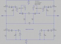
1. I have a couple of LL1690 input transformers(10k:10k) which has higher impedance per winding(150 ohm) compare to Jensen transformer. Do you think it will affect the sound or the stability of F6? Do I need to change the components values?
2. In the F6 schematics, is there any reason the bias voltage is injected into the bottom side of the secondary windings? Connecting bias to the gate directly will make any differences?
3. Could anybody please explain why C1 is connected to the output instead of ground? I am sure the question is from my ignorance about quasi complementary push pull pair, but I really want to understand the circuit.
Thank you
I am planning to build F6 and have some questions and need your advise.
1. I have a couple of LL1690 input transformers(10k:10k) which has higher impedance per winding(150 ohm) compare to Jensen transformer. Do you think it will affect the sound or the stability of F6? Do I need to change the components values?
2. In the F6 schematics, is there any reason the bias voltage is injected into the bottom side of the secondary windings? Connecting bias to the gate directly will make any differences?
3. Could anybody please explain why C1 is connected to the output instead of ground? I am sure the question is from my ignorance about quasi complementary push pull pair, but I really want to understand the circuit.
Thank you
1. nothing prevents you from trying , even if final issue can be slightly different top end response , comparing to use of plain repeater
2. it's more elegant ( read - simpler ) this way
3. think dynamically - cap is short for AC ; what's happening when upper mosfet's source goes up ? and then remember that biasing is nothing else than applying steady voltage between source and gate ......... while modulating is applying AC voltage in same place
1. I have a couple of LL1690 input transformers(10k:10k) which has higher impedance per winding(150 ohm) compare to Jensen transformer. Do you think it will affect the sound or the stability of F6? Do I need to change the components values?
>>Not a transformer expert. It will work but these will have higher capacitance and higher inductance, so rolls off faster at higher end but perhaps a little more bass at lower end.
2. In the F6 schematics, is there any reason the bias voltage is injected into the bottom side of the secondary windings? Connecting bias to the gate directly will make any differences?
>>I have wondered the same thing myself - iirc nelson says it works a little better this way. Can't find the post where he discusses it so my memory be be faulty.
3. Could anybody please explain why C1 is connected to the output instead of ground? I am sure the question is from my ignorance about quasi complementary push pull pair, but I really want to understand the circuit.
>> If you ground it, the top FET will behave as a follower thus destroying the symmetry between the top and bottom halves.
>> BTW the F6 is not a quasi-comp. In the usual quasi-comps, the output devices do not behave symmetrically - with one having voltage and current gain and the other only providing current gain. Parts are needed ahead of the output devices to address this imbalance. Nelson's F6 circuit solves these problems very elegantly.
- Home
- Amplifiers
- Pass Labs
- F6 Amplifier