")
We're working on two different instructions. One will be the long term version with the clearest, and slickest production values, the other will hopefully be done very soon and will be a bit looser.
Of course you should read the article a couple of times. It live in the menu bar at the top of the page under "articles" or here:
http://www.diyaudio.com/index.php?pageid=articles
Of course you should read the article a couple of times. It live in the menu bar at the top of the page under "articles" or here:
http://www.diyaudio.com/index.php?pageid=articles
Got my kit, very excited. Do you guys know when the step by step photo instructions will be available? I'm a total newbie here.
Thx!
Last edited:
Is any matching needed for the mosfets ot jfets? Is there any benefit from matching and if so do the kits have matched transistors??
Nelson Pass really thought this through. And it being Single-Ended helps. The JFET input buffer is just one JFET, so no matching there, and the output device is a single MOSFET. It has a second MOSFET but that's for a different function- the constant current source, so no matching required or possible.
Last edited:
...... or possible.
do not underestimate creativity of common Greedy Boy .........

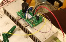
I got my kit and built it and I am listening to it now. I will write a review, at some point, as I have solicited reviews from others. I am attaching some photos.
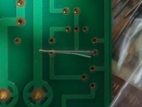
In the first photo you can see the built- up kit, there are some switches and binding-posts in the kit as well which are not yet attached in the photo. The board in the photo is powered-up I was adjusting the offset cold. It did not change much (only a few mV) when they got hot.
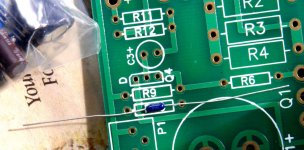
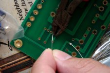
There are people that can stuff PCBs a lot neater then I can using special jigs to bend the leads I am sure there are some more detailed tutorials on this site. As can be seen from the pictures, I place the component (resistor in this case) on the board to get an idea of where to bend the leads. Then I use the needle nose pliers to bend the lead, never putting any pressure on the component side and making sure the value is facing up. If the spacing is right it should slide right into the board. I then bend the leads on the back side of the board so it does not slide out while I am soldering. Then the leads get clipped with wire cutters, holding on to the lead so it will not go flying.
These resistors seem a bit small to be 1/4Watt (I'm not sure what they are actually) I was actually expecting the brown Dale resistors. I just went ahead and use them, and there were no problems.
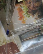
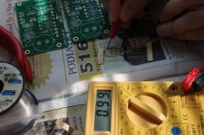
I got all parts needed to build the kit. However one strip of resistors was marked 1K on one side and 10K on the other, so just watch-out for that. I measured everything with a multimeter. You can see me measuring the resistors in the picture and in another pic you can see the 1K marking on the other side.
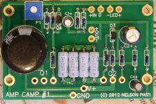
If there are any questions as to where or how components go, I am attaching a high resolution picture of the board. You should be able to see the markings on all the resistors.
Good luck to others,
Leve
In the first photo you can see the built- up kit, there are some switches and binding-posts in the kit as well which are not yet attached in the photo. The board in the photo is powered-up I was adjusting the offset cold. It did not change much (only a few mV) when they got hot.
There are people that can stuff PCBs a lot neater then I can using special jigs to bend the leads I am sure there are some more detailed tutorials on this site. As can be seen from the pictures, I place the component (resistor in this case) on the board to get an idea of where to bend the leads. Then I use the needle nose pliers to bend the lead, never putting any pressure on the component side and making sure the value is facing up. If the spacing is right it should slide right into the board. I then bend the leads on the back side of the board so it does not slide out while I am soldering. Then the leads get clipped with wire cutters, holding on to the lead so it will not go flying.
These resistors seem a bit small to be 1/4Watt (I'm not sure what they are actually) I was actually expecting the brown Dale resistors. I just went ahead and use them, and there were no problems.
I got all parts needed to build the kit. However one strip of resistors was marked 1K on one side and 10K on the other, so just watch-out for that. I measured everything with a multimeter. You can see me measuring the resistors in the picture and in another pic you can see the 1K marking on the other side.
If there are any questions as to where or how components go, I am attaching a high resolution picture of the board. You should be able to see the markings on all the resistors.
Good luck to others,
Leve
Attachments
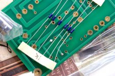
Looks very good! The little resistors are 1/4w . They actually cost more than the bigger Dales which are 1/2w. We'll probably go with the 1/2 watt eventually, mostly because that way it's easier to read the markings, and that's the best thing about them- they say their value right on them!
We're working on two different instructions. One will be the long term version with the clearest, and slickest production values, the other will hopefully be done very soon and will be a bit looser.
Thanks, Variac
Amp Camp Review
Associated Equipment:
Amplifiers:
Speakers:
Preamp: None
First some comments:
This is my subjective opinion, it may change over time, with different equipment, listening material and so on. In the past I have built some pre-amps, power supplies for class-d amp boards and finished some Twisted Pear Audio dacs and so on (using the Twisted Pear USB DAC/Receiver for this review). So that “I can’t believe I built that” feeling has worn off now, where even a tin can connected by a string can beat a 100k system. I am not afraid to speak my mind and call things as I see them. As proof on this very thread user 6L6 told me I should “go kill myself”, though it was removed by the moderator. So please don’t assume I am holding back anything. Finally I have no financial interests, I have never met Mr. PASS in person, and I bought my Amp Camp project just like everyone else in the hopes of good sound.
Getting on with it:
The Amp Camp manages to grip the base notes very nicely. One of the problems many highly regarded amps seem to have with full range drivers is getting them to produce any reasonable base. The current thinking here is that these amps are designed as stiff voltage sources and ignore the impedance bump the speaker shows the amplifier so even if the amp is capable of hundreds of watts the balance is still wrong. The amp camp seems well balanced in this regard it can use its watts for what they were intended for.
I once accidently connected the 300B Bravo putting the 8ohm Tektons on the 4ohm tap so the tube is seeing a 6K load as opposed to a 3K. I am not sure why but there was a lot of base way too much base where it sounded unpleasantly unbalanced. I like British mysteries and I was viewing (and listening to) Wallander “An Event in Autumn”. It is available until tomorrow (Oct, 9. free for online viewing at PBS). The beginning seen with the girl on the ship is very base heavy and the misconnected 300b gave me some wow factor, sort of like wow I didn’t know my speakers could do that. But as we got into the dialog everyone sounded too chestty and the amusement quickly wore thin making me reconnect the speakers to the 8ohm tap. Here the Amp Camp and the 300b have about the same amount of base. The amp camp might have a hair more actually, but you would only notice in quick A/B listening. The amp camp is listed as 5watts and the 300b is listed as 8watts so again it’s making me think this is more damping factor related. My other amp the 6p13p has a little less base but its output transformers are also much smaller. Both the 300b and Amp Camp have tight base the Amp Camp is a bit stiffer at the front of the stroke where the 300b is a bit wetter and 6p13p has a smoother base.
In the midrange department the 6p13p sounds most natural. The 300b even properly connected sounds too chestty at the expense of being a bit rolled off on the top which is why I use it less. The Amp Camp is very clear having a lot of attack, I was actually surprised for an SE topology I was expecting a bit smoother mid-range which I actually prefer, but this is mostly personal taste. The softening of the mid-range with the 6p13 makes the volume level a bit less important, with the Amp Camp my hand was on the volume knob a bit more. I have a DVD I bought at the Met of The Magic Flute an English edition (it was actually recorded just 50miles from my house). When Tamino has his meeting with the Queen of the Night and the three spirits give Tamino the flute and Papageno the bells and there being sent off to find Sarastro having to follow the bird, the music from the orchestra gets very delicate and you can hear the actors stepping on the floor boards, and the floor boards creaking. The Amp Camp seems to highlight that with nice clear detail, as where some other amps I have owned tend to gloss over it. On some older recordings where the sound was a bit washed out the 6p13p made recording sound even more washed out (going in the wrong direction) and the Amp Camp gave it just what it needed, a little bit of livening up. On the other hand on some Inspector Morse episodes certain words such as “truth” for example had a sharp Sssss type sound at the back of them with the Amp Camp. However this only happened on a small number of recordings. This is unfortunately the way of things no one amp can do it all. Some amps work best with some recordings and other amps work well with other recordings so the 6p13p and Amp Camp though being different come out even here.
Looking at the top end both the Amp Camp and 6p13p have excellent and nicely extended top end that goes as far as the speakers can handle (I haven’t measured, just going by ear) I feel the Amp Camp edges out the 6p13p for top-end extension, I’ll bet that jfet on the input stage has a lot to do with that, though strangely they seem to highlight different events at the top. The 300b is a bit rolled off in the top which is one of my major objections to it. Does anyone know if this is representative of the breed? I find myself chucking a lot of amps on account of high end problems. Most recently I chucked an TDA8920 class-d board because the top end was tizzy. One of the ways I like to check this is on the Inspector Morse episode “Death Is Now My Neighbor” in a seen towards the back when Morse is talking to Adel I ask myself if I notice the clock in the room. The Amp Camp passes the test.
It’s hard for me to tell about imaging because I lack space to set up my speakers as optimally as I would want. So I will not comment here.
What to take away from this review. The Amp Camp is fairly clear for an amp of the single ended persuasion. The frequency response is nicely balanced from bottom to top so build with confidence. You don’t notice any distortion in the way of rosiness softening of the edges which may or may not be your cup of tea. This kind of surprised me when looking at the distortion plot. The amp camp beats my 300B hands down and the 6p13p is more of a question of taste. I could listen to it for an extended period of time.
Leve
Associated Equipment:
Amplifiers:
1) The Amp Camp amplifier (no intro needed)
2) Bravo 2.2 this is 6sj7 -> 300B no feedback, beefy output transformers, DC filaments, originally came stocked with 6J4P (Pentode) -> 300b
3) 6sj7 -> 6p13p (similar to 6L6) in UL mode SE amp with global feedback
2) Bravo 2.2 this is 6sj7 -> 300B no feedback, beefy output transformers, DC filaments, originally came stocked with 6J4P (Pentode) -> 300b
3) 6sj7 -> 6p13p (similar to 6L6) in UL mode SE amp with global feedback
Speakers:
4) Tekton Design Model 6.5, it is a full-range Fostex FE167E (94db\Watt) sadly Tekton doesn’t make them anymore.
Dac: Twisted Pear USB DAC/ReceiverPreamp: None
First some comments:
This is my subjective opinion, it may change over time, with different equipment, listening material and so on. In the past I have built some pre-amps, power supplies for class-d amp boards and finished some Twisted Pear Audio dacs and so on (using the Twisted Pear USB DAC/Receiver for this review). So that “I can’t believe I built that” feeling has worn off now, where even a tin can connected by a string can beat a 100k system. I am not afraid to speak my mind and call things as I see them. As proof on this very thread user 6L6 told me I should “go kill myself”, though it was removed by the moderator. So please don’t assume I am holding back anything. Finally I have no financial interests, I have never met Mr. PASS in person, and I bought my Amp Camp project just like everyone else in the hopes of good sound.
Getting on with it:
The Amp Camp manages to grip the base notes very nicely. One of the problems many highly regarded amps seem to have with full range drivers is getting them to produce any reasonable base. The current thinking here is that these amps are designed as stiff voltage sources and ignore the impedance bump the speaker shows the amplifier so even if the amp is capable of hundreds of watts the balance is still wrong. The amp camp seems well balanced in this regard it can use its watts for what they were intended for.
I once accidently connected the 300B Bravo putting the 8ohm Tektons on the 4ohm tap so the tube is seeing a 6K load as opposed to a 3K. I am not sure why but there was a lot of base way too much base where it sounded unpleasantly unbalanced. I like British mysteries and I was viewing (and listening to) Wallander “An Event in Autumn”. It is available until tomorrow (Oct, 9. free for online viewing at PBS). The beginning seen with the girl on the ship is very base heavy and the misconnected 300b gave me some wow factor, sort of like wow I didn’t know my speakers could do that. But as we got into the dialog everyone sounded too chestty and the amusement quickly wore thin making me reconnect the speakers to the 8ohm tap. Here the Amp Camp and the 300b have about the same amount of base. The amp camp might have a hair more actually, but you would only notice in quick A/B listening. The amp camp is listed as 5watts and the 300b is listed as 8watts so again it’s making me think this is more damping factor related. My other amp the 6p13p has a little less base but its output transformers are also much smaller. Both the 300b and Amp Camp have tight base the Amp Camp is a bit stiffer at the front of the stroke where the 300b is a bit wetter and 6p13p has a smoother base.
In the midrange department the 6p13p sounds most natural. The 300b even properly connected sounds too chestty at the expense of being a bit rolled off on the top which is why I use it less. The Amp Camp is very clear having a lot of attack, I was actually surprised for an SE topology I was expecting a bit smoother mid-range which I actually prefer, but this is mostly personal taste. The softening of the mid-range with the 6p13 makes the volume level a bit less important, with the Amp Camp my hand was on the volume knob a bit more. I have a DVD I bought at the Met of The Magic Flute an English edition (it was actually recorded just 50miles from my house). When Tamino has his meeting with the Queen of the Night and the three spirits give Tamino the flute and Papageno the bells and there being sent off to find Sarastro having to follow the bird, the music from the orchestra gets very delicate and you can hear the actors stepping on the floor boards, and the floor boards creaking. The Amp Camp seems to highlight that with nice clear detail, as where some other amps I have owned tend to gloss over it. On some older recordings where the sound was a bit washed out the 6p13p made recording sound even more washed out (going in the wrong direction) and the Amp Camp gave it just what it needed, a little bit of livening up. On the other hand on some Inspector Morse episodes certain words such as “truth” for example had a sharp Sssss type sound at the back of them with the Amp Camp. However this only happened on a small number of recordings. This is unfortunately the way of things no one amp can do it all. Some amps work best with some recordings and other amps work well with other recordings so the 6p13p and Amp Camp though being different come out even here.
Looking at the top end both the Amp Camp and 6p13p have excellent and nicely extended top end that goes as far as the speakers can handle (I haven’t measured, just going by ear) I feel the Amp Camp edges out the 6p13p for top-end extension, I’ll bet that jfet on the input stage has a lot to do with that, though strangely they seem to highlight different events at the top. The 300b is a bit rolled off in the top which is one of my major objections to it. Does anyone know if this is representative of the breed? I find myself chucking a lot of amps on account of high end problems. Most recently I chucked an TDA8920 class-d board because the top end was tizzy. One of the ways I like to check this is on the Inspector Morse episode “Death Is Now My Neighbor” in a seen towards the back when Morse is talking to Adel I ask myself if I notice the clock in the room. The Amp Camp passes the test.
It’s hard for me to tell about imaging because I lack space to set up my speakers as optimally as I would want. So I will not comment here.
What to take away from this review. The Amp Camp is fairly clear for an amp of the single ended persuasion. The frequency response is nicely balanced from bottom to top so build with confidence. You don’t notice any distortion in the way of rosiness softening of the edges which may or may not be your cup of tea. This kind of surprised me when looking at the distortion plot. The amp camp beats my 300B hands down and the 6p13p is more of a question of taste. I could listen to it for an extended period of time.
Leve
R12 value for 6.5ohm output impedance?
Up front, my apologies. I struggled tremendously in my college electrical engineering course, mostly because I lack the math skills to calculate the component values.
Mr. Pass's "thumbnail calculation" yielded 100K ohm for R12 to get a 6.5ohm output impedance. But he later posted "Without the R12/R11 loop, the output impedance of the amplifier is 10 ohms. To get 6.5 ohms, apply a little over 3 dB of feedback to take the gain down to about 20 dB. Probably my estimate of 100K was a little low for R12."
So what should R12 be to get a 6.5ohm output impedance? (Because I'd LOVE to build this amp and a set of Arpeggio loudspeakers... seems like a great match.)
OK, I went through the same thing.There were various "seat of the pants" estimates of how to achieve around 6.5 ohm output impedance. Then a friend N-Brock used the lovely bunch of formulas Morgan Jones gives showing how he calculated his speaker parameters to adjust for the new version of driver, as the old driver has been replaced. The result was that the cabinet needs to be about 25% bigger. More than we expected but doable- but I'd like to revisit those calcs before cutting wood..
But then we played around with the response, and it seems that even a half ohm makes a huge difference in the bass response. As Morgan said it is a big advantage that the amps have a relatively high output impedance
Now I'm wondering if the Tube guys know their output impedance because they have output transformers, which maybe are rated at say 6.5 ohms. Is that true? If so then getting the S.S. output impedance might be pretty tricky.
Maybe the best thing is to do as Morgan suggests and add a resistor inline with the speaker cable. Get a handful of resistors that can be combined from say 3 ohms to 7 ohms until things sound about right. I need to review how to get the exact amp impedance, but I remember it seemed daunting. Any help?
Last edited:
Measuring is more accurate.
Try this:
1) Pick a feedback value
2) Run a sine wave through the amp any Hz in the audio range will do so long as the amplitude is constant.
3) Measure the ac output voltage of the Amp Camp with no load. Let’s call that Vu.
4) Put a dummy resistor load (not a speaker) on the output of the amp say something between 4-12hohms call this value whatever you pick RL
5) Then measure the ac output voltage again with the load call this VL
6) Then calculate Zo = (Vu - VL) / (VL / RL)
7) See what you get if you want more Zout bring the feedback resistor value up if you want less bring it down and measure again
***Don’t forget to make sure it’s not clipping when you do this, else the Zout will be wrong.
I wonder what it sounds like without any feedback. Oh well too late to find out now unless I unsolder the resistor and get covered in silicone grease.
Last edited:
- Home
- Amplifiers
- Pass Labs
- Amp Camp Amp - ACA