Does that lead to best amp - no amp?best PSU is - no PSU


A group or a mosaic photo [if any] for the members of DIYAudio to E-meet the principals.I often quote myself as I find it adds spice to my conversation.
Oh look! I found a couple of stills from the Amp Camp footage.
On the left, moderator Variac and on the right Jason, the founder of DIYAudio.

A thumbnail calculation sez that R12 = 100K would just about do it.
Does anybody know how that was calculated? The only thing I know (or think I know) is that without feedback (infinite value for R12) it would be a current source (tapped at the drain of Q1) which would be close to an infinite output resistance. But the gain would be too high and distortion would be much higher without a resistor on the source of Q1 which is also a kind of feedback. The gain is R12/R11.
Does anybody know how that was calculated?
Yes, I do. I looked at my thumbnail and in it I saw a reflection of the resistor
bins, noting that I had 100K and 150K available. 150K seemed a bit high,
although you might want to try it.
Infinite R12 was measured in the article, and the gain was 23 dB.
Last edited:
Does anybody know how that was calculated? The only thing I know (or think I know) is that without feedback (infinite value for R12) it would be a current source (tapped at the drain of Q1) which would be close to an infinite output resistance. But the gain would be too high and distortion would be much higher without a resistor on the source of Q1 which is also a kind of feedback. The gain is R12/R11.
An ambitious bolded statement. Looking at the output node [opposed drains], and in the abscence of loop feedback, the resistance of the gain MOSFET[lower] is 9.5 Volts divided by the current flowing thru it; for example 1 Amp = 9.5 Ohms. Ditto for the MOSFET [upper] of its load = 9.5 Ohms too since it has identical static conditions. The load sees two resistors in parallel [one to ground and the other to AC ground at 19 VDC] each of which is 9.5 Ohms; for a net equivalent resistance of ~4.8 Ohms. It is high compared to the output impedance of a classical voltage source amp ~<0.1 Ohm. Loop feedback further lowers this 4.8 Ohm output Z, and extends power bandwidth. Distortion is low before loop feedback because the output stage is sliding/operating on a linear portion of its load line. Loop feedback linearizes further its operation.
Oh I never thought of it that way (power devices as resistors). I guess it makes sense. I assume this implies output resistance and there by the damping factor also depends on the rail voltage and bias current. We could also assume without adding a resistor on the output we cannot make output Z higher than 4.8 ohm.
Would I be correct in assuming the reduction in output resistance can be calculated? If I look at the open loop gain of 23dB(14.1x) and the closed loop gain 14dB(5x) and if we take your 4.8 Ohm output Z. Then we could assume 14.1 * 4.8 / 23 = 2.9 Ohm output Z, which is fairly near to the stated output Z of Mr. Pass of 2.9 ohms calculated from the stated damping factor of 3 = 8ohm speaker / 2.6ohm DF.
So I guess my gain formula is wrong for values higher than the amps open loop gain. I forgot to take that into account. Woops. I blame high gain opamps.
Would I be correct in assuming the reduction in output resistance can be calculated? If I look at the open loop gain of 23dB(14.1x) and the closed loop gain 14dB(5x) and if we take your 4.8 Ohm output Z. Then we could assume 14.1 * 4.8 / 23 = 2.9 Ohm output Z, which is fairly near to the stated output Z of Mr. Pass of 2.9 ohms calculated from the stated damping factor of 3 = 8ohm speaker / 2.6ohm DF.
So I guess my gain formula is wrong for values higher than the amps open loop gain
. I forgot to take that into account. Woops. I blame high gain opamps.Perhaps it's worth working through this a bit. The IRFP240 Mosfet has
a transconductance of about 2 when biased at 1 amp. This means that
2 amps of current flows for every volt of input at the Gate. So for our
purposes at the moment we will treat it as a Mosfet of infinitely high
transconductance with a Source resistor of 0.5 ohms. Since this circuit
does not supply an external resistance between the Source pin and ground,
that is all we need for a quick calculation.
If the output resistance (Plate resistance if this were a tube) was infinite,
then the gain into an 8 ohm load would be 8/0.5 = 16X, which is 24 dB.
But it's more complicated than that. The Mu follower current source on
top of the circuit also contributes to gain, adding maybe 5 dB. So now
we estimate that with infinite Drain resistance the gain is 29 dB, which is
28X.
OK so far?
But we actually experience 23 dB gain due to the finite Drain resistance(s)
and the contribution of the DC feedback loop. This 5 dB drop is a factor
of 0.56X, and is equivalent to our high Drain resistance example driving
8 X 0.56, which is 4.5 ohms.
So now we have an apparent Drain resistance which is equivalent to that
value which paralleled with 8 ohms gives us 4.5 ohms. That resistor is
close to 10 ohms.
Without the R12/R11 loop, the output impedance of the amplifier is 10
ohms. To get 6.5 ohms, apply a little over 3 dB of feedback to take the
gain down to about 20 dB. Probably my estimate of 100K was a little low
for R12.
19V single ended for 5W...
ahh
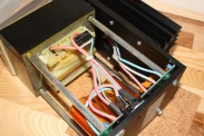
been looking at this regulated power supply, not knowing what to do with it
a friend dropped it on my doorstep
0-24V, 10A
Attachments
Woow it seems like finding the output Imp. is pretty complicated.
Steps
1)find the transconductance at your biased current
2) calculate your theoretical expected open loop gain
3) measure actual open loop gain
4) calculate missing gain and equivalent resistance end then output impedance
5) calculate for correction of feedback
The amp camp amp is working already, I'm learning something new.
Thank you Mr. Pass
Woow it seems like finding the output Imp. is pretty complicated.
Steps
1)find the transconductance at your biased current
2) calculate your theoretical expected open loop gain
3) measure actual open loop gain
4) calculate missing gain and equivalent resistance end then output impedance
5) calculate for correction of feedback
The amp camp amp is working already, I'm learning something new.
Thank you Mr. Pass
If I may add to the above in the abscence of loop feedback. The Resistance of the gain MOSFET = 9.5 V divided by 1 Amp = 9.5 Ohms. The upper MOSFET [mu follower] is a constant current source of very high impedance; i.e. >>>10 Ohms. After all, we all believe [and grew up with the concept] that a CCS defies Ohm's law; but appears to be intrinsically very high resistance. It does not count here relative to 9.5 Ohms. So, looking in the output node, two resistive paths are evident in parallel: 9.5 Ohms//may be 1000 Ohms for example [ignore it]. One is left with 9.5 Ohms or 10 Ohms [1 significant figure]; like the calculated result of Mr. Pass.
Well this does point out that the amps are so small and cheap that multi-amping might be a great strategy. Especially with active or passive crossovers at the amp inputs- the amp only "sees" the one driver.
Its looking like a classic... thinking of some crazy idea? Make a couple of ACA's and try it out!
Its looking like a classic... thinking of some crazy idea? Make a couple of ACA's and try it out!
14db gain, 5watt
me think compression driver
Last edited:
Its looking like a classic... thinking of some crazy idea? Make a couple of ACA's and try it out!
also have some 'smaller' heatsinks
ehh, schematic shows + output at ground
I suppose it means phase inverting output
- Home
- Amplifiers
- Pass Labs
- Amp Camp Amp - ACA