Good Evening Mooly
hmm... yes you are right. strange..
because of this diode in the first transistor Q4.
i think that this K30A FET what was at this kit is maybe the reason. i found just this datasheet...i am not sure if i have the GR version, means with 2,6...6,5mA.
chris
The board has Q4 marked as (2S)K246. That is what came with the kit I had. Though I did not use any of those parts in my build.
Yup!
....Is the Bryston's XLR pin assignment compatible with the ACAs'? .....
Hi alan
i try to get other to92 J-fets and this Ztx.
thx
Chris,
Just note that the ZTX450 pin out is different to the BC550.
(ZTX = e-b-c vs BC = c-b-e)
and the 2SK170 pin out is different to the K246 (K30A).
('K170 = d-g-s vs 'K246 = s-g-d)
They both fit in the board 180 degrees from the shape printed on the board.
Alan
Quick noob question...
While working on the ACA build, I have just noticed (too late) that Jim in his great guide states:
So... how important is it to have some air gap between the 3W resistors and the PCB?
Would it be a pure cosmetic issue (discolored PCB)? or could it cause a malfunction eventually?
Right now, I can either just leave it as is (resistors barely touch PCB) or buy new resistors tomorrow and replace the soldered ones. I have only soldered 2 of the 8 high power 3W resistors, so still relatively easy to fix!
While working on the ACA build, I have just noticed (too late) that Jim in his great guide states:
Power resistors: They do get hot and over a long period of time might discolor the PCB. Put a spacer underneath them (like a piece of cardboard) to create an air gap of a few mm, and remove it after soldering them in place.
So... how important is it to have some air gap between the 3W resistors and the PCB?
Would it be a pure cosmetic issue (discolored PCB)? or could it cause a malfunction eventually?
Right now, I can either just leave it as is (resistors barely touch PCB) or buy new resistors tomorrow and replace the soldered ones. I have only soldered 2 of the 8 high power 3W resistors, so still relatively easy to fix!
It is purely cosmetic and caused by reaction of the board material to heat. The resistors actually dissipate little power, yes the current is high but the resistance is low and so the power is low.
The 0.68 ohms will be hottest but still come in under 0.5 watt dissipation.
e.g. current of 1.6 A split equally between the two is 0.8amp per resistor.
Power is current squared multiplied by resistance and so you get (0.8*0.8)/0.68 which is well under 0.5 watts
The 0.68 ohms will be hottest but still come in under 0.5 watt dissipation.
e.g. current of 1.6 A split equally between the two is 0.8amp per resistor.
Power is current squared multiplied by resistance and so you get (0.8*0.8)/0.68 which is well under 0.5 watts
Yup!
Thank you! I'm listening to them now. Brubeck's Take Five on SACD played through my Oppo BDP-105, the Bryston preamp, and KEF LS-50s. I'll switch to Vandersteen IICE Sigs after a while to see how they do with them.
So far, the ACAs seem a little brittle on top compared to the Bryston 4B SST that I usually use. 300 W/channel versus 15 W/channel isn't quite fair but the difference isn't as great as I imagined it might be, especially as the ACAs have been used for less than an hour altogether. I wonder if they'll sound much different after 20-30 hours.
ACA signal ground to chassis?
Hi,
Beginner question - I plan to build an ACA with linear power supply in the chassis and I have a grounding question. Obviously the mains earth ground will be connected to the chassis at the IEC entry module for safety. There seems to be some mild disagreement about whether the power supply ground (on the secondary side) should be connected to the chassis ground, but the standard First Watt recommendation seems to be to connect it through a 10R thermistor. I'll do that - I understand the rationale for doing so.
But what about the signal ground on the ACA board? Should that be connected to the chassis ground? I have been reading forums for some time now, am I correct that there is widespread disagreement about this?
Out of curiosity, and I know this isn't the same situation because the ACA kit uses an external SMPS, but how come version #1 of the board had signal ground connected to chassis through the standoffs, v1.1 removed the plated mounting holes, and then v1.6 put them back in?
If it's true that there's a lot of disagreement on this point then I'm happy to experiment. It is DIY after all.
It is purely cosmetic and caused by reaction of the board material to heat. The resistors actually dissipate little power, yes the current is high but the resistance is low and so the power is low.
The 0.68 ohms will be hottest but still come in under 0.5 watt dissipation.
e.g. current of 1.6 A split equally between the two is 0.8amp per resistor.
Power is current squared multiplied by resistance and so you get (0.8*0.8)/0.68 which is well under 0.5 watts
Thanks Mooly
")
So far, I have only soldered the 0.47 ohms 3W resistors, so will keep it as-is.
Will definitely keep a little air gap when soldering the 0.68 ohms resistors.
Follow up question:
What about the 1R 3W resistors in the ACP+ design?
The current there is MUCH lower (less than 0.5A)
Follow up question:
What about the 1R 3W resistors in the ACP+ design?
The current there is MUCH lower (less than 0.5A)
I guess power would be less than 0.5*0.5 = 0.25W. Right?
So I guess no need to replace the 1R resistors there and add air gap between the resistors and PCB...
Follow up question:
What about the 1R 3W resistors in the ACP+ design?
The current there is MUCH lower (less than 0.5A)
I'm not familiar with that one but yes, 0.5A in 1 ohm is just 0.25 watt dissipation as Zachik says.
Why are the resistors so big in wattage terms then?
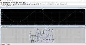
Well in the ACA the current in those resistors varies with signal and load impedance. Over a cycle of a sine wave the current can increase significantly over the steady state condition during the first 180 degrees and then it falls during the second 180 degrees.
This shows the current in one of the 0.68 ohm resistors under worst case conditions, a 4 ohm load and almost at clipping. The current actually approaches near to zero over the second half of the sign.
Attachments
I'm not familiar with that one but yes, 0.5A in 1 ohm is just 0.25 watt dissipation as Zachik says.
Why are the resistors so big in wattage terms then?
Well in the ACA the current in those resistors varies with signal and load impedance. Over a cycle of a sine wave the current can increase significantly over the steady state condition during the first 180 degrees and then it falls during the second 180 degrees.
This shows the current in one of the 0.68 ohm resistors under worst case conditions, a 4 ohm load and almost at clipping. The current actually approaches near to zero over the second half of the sign.
Does that mean that momentarily the current would reach 1.4A (peak of the sine wave you're showing)?
So peak power would be 1.4*1.4*0.68 = 1.33W?
The only resistors I soldered to touch the PCB are the 0.47 ohms, so peak power would be 1.4*1.4*0.47 = 0.92W? I wonder if that is enough to warrant replacing the 0.47 ohms resistors? Leads were already clipped, so I cannot just heat the joint and pull gently to add air gap
as a matter of practice, power resistors are mounted off board by at least 3mm to provide air circulation around the resistors...
Sound of Capacitor Energizing
When I start my ACA as a stereo amp using the RCA inputs, I can hear the big capacitor energizing. But when I start my ACA in bridged mono using the XLR input, I don't hear the capacitor. Is this because the XLR is balanced and the RCAs are single-ended?
Jim
When I start my ACA as a stereo amp using the RCA inputs, I can hear the big capacitor energizing. But when I start my ACA in bridged mono using the XLR input, I don't hear the capacitor. Is this because the XLR is balanced and the RCAs are single-ended?
Jim
When I start my ACA as a stereo amp using the RCA inputs, I can hear the big capacitor energizing. But when I start my ACA in bridged mono using the XLR input, I don't hear the capacitor. Is this because the XLR is balanced and the RCAs are single-ended?
Jim
It is because both power amps experience the same rise in voltage at their outputs when you switch on and so the difference between them (which is where the speaker connects) is effectively zero.
For example if you connect a speaker across 1000 a volt supply it will go bang, but if you connect it between two identical 1000 volt supplies there is then no voltage difference between them... so no noise or anything from the speaker.
- Home
- Amplifiers
- Pass Labs
- Amp Camp Amp - ACA